Guide
CAM Software: How It Works and How to Choose
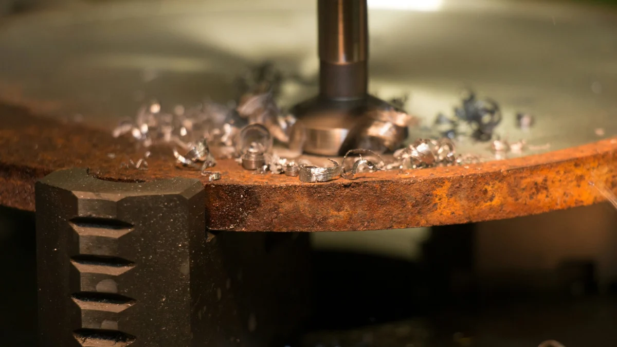
CAM (Computer Aided Manufacturing) software turns a part model into a program for the machine tool: from CAD geometry it generates toolpaths, checks them in simulation and, through a postprocessor, writes them as G-code for a specific machine. In this guide we explain how a CAM system works, what functions it offers, how SolidCAM, Mastercam, hyperMILL, WORKNC and VISI differ, and how to choose CAM software for your own machine park.
CAM: computer-aided manufacturing
CAM stands for computer-aided manufacturing: software that plans machining and prepares control data for CNC machines. In everyday shop practice it is the program that takes a 3D model or a drawing, builds the operations, selects tools, calculates toolpaths and hands a finished file to the machine control.
Encyclopaedia Britannica describes Computer Aided Manufacturing as the use of computers to plan, control and manage production, and calls the combination of design and manufacturing engineering simply CAD/CAM. The story begins after the Second World War: the MIT Servomechanisms Laboratory built the first numerically controlled milling machine, and from 1956 a team led by Douglas T. Ross developed the APT language there for automatic programming of machine tools. In 1957 Patrick Hanratty wrote PRONTO at General Electric, regarded as one of the first commercial numerical control programs.
CAD, CAM and CAE: three layers of one process
CAD, CAM and CAE are three layers of one process. CAD (Computer Aided Design) is used to design geometry, CAE for engineering analysis such as strength, flow and vibration, and CAM for machining technology. A change to the model in CAD carries over to CAM, which recalculates the toolpaths without redrawing everything from scratch.
For a machining shop the CAM layer matters most, because it determines machine time and part quality. CAE is mostly useful to designers, although some packages now also calculate tool load and vibration during cutting.
How a CAM system works: from model to G-code
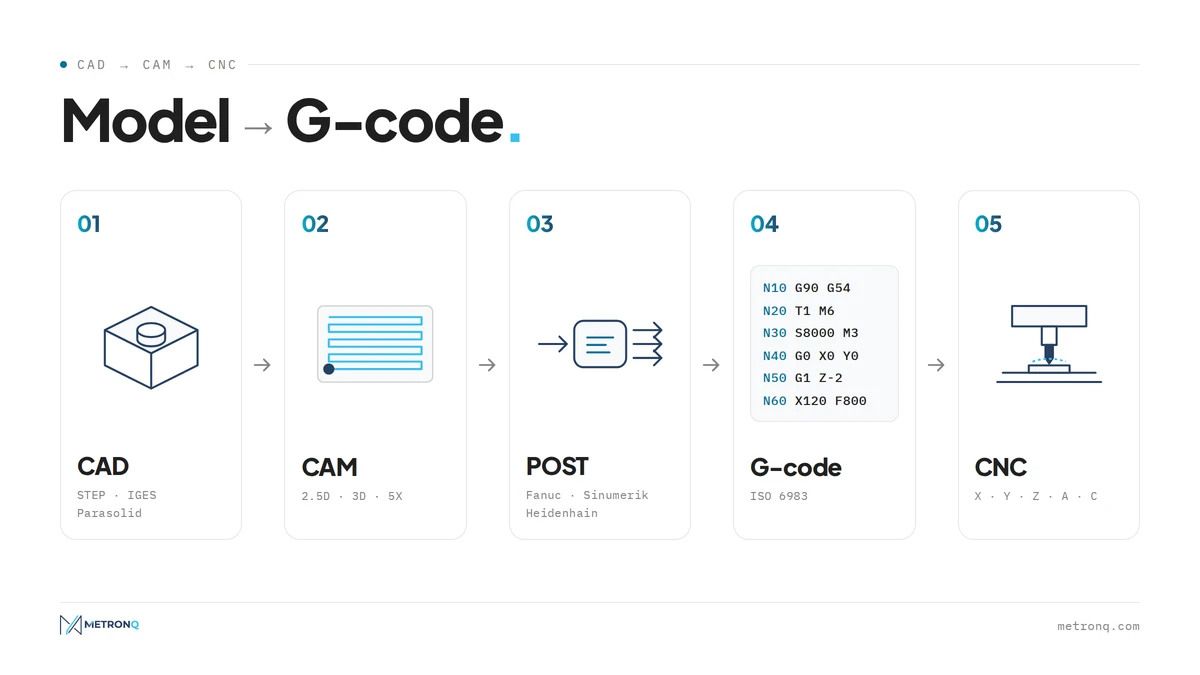
A CAM system takes the programmer through a fixed sequence of steps: importing the model, setting the datum and stock, choosing tools, planning operations, generating toolpaths, simulation and postprocessing. The result is a G-code file in ISO 6983 format that goes straight to the machine control.
- Model import. Usually STEP, less often IGES or Parasolid. The STEP AP242 format already carries tolerances and annotations directly in the model, which according to NIST cuts the time spent re-entering data from drawings.
- Datum and stock. The part coordinate system, the fixturing and the size of the raw blank, from which the material to be removed is calculated.
- Tool library. Cutters, drills and holders with their dimensions, stick-out and cutting parameters.
- Operations and toolpath generation. Facing, pockets, contours, drilling, threading; the program calculates the trajectory with approaches, entries and linking moves.
- Simulation and postprocessing. A collision check, then output of the toolpaths in the language of a specific control.
The last step is handled by the postprocessor, which converts the neutral toolpath data from CAM into G-code that a particular machine and control understand. In its postprocessor guide, Autodesk explicitly recommends a separate postprocessor for each machine tool, because one control supports circular interpolation while another needs arcs broken into line segments.
Generating toolpaths is only half the job: a good postprocessor is what lets a CAM program run on the machine without manual edits. How to read the resulting code is covered in our article on G-code and CNC programming.
CNC machining simulation in a CAM program shows material removal and collisions between the tool and the part, but it usually checks the toolpath before postprocessing. Full machine simulation reads the finished G-code the way the control does, with the machine kinematics, fixtures and axis limit switches.
The second method catches errors the first cannot see: an axis running out of travel, the head hitting the table or a bad approach in 5-axis machining. With expensive parts and multi-axis machines, simulating CNC machining on G-code costs less than a single crashed spindle.
Main functions of CAM software
The main functions of CAM software are 2.5D, 3D and 5-axis machining strategies, turning and mill-turn, EDM, simulation, tool libraries and postprocessors. Systems differ less in the feature list, which looks similar everywhere, than in the quality of their roughing strategies, ease of use and support for specific machines.
| Function | What it is for |
|---|---|
| 2.5D machining | pockets, contours and drilling in prismatic parts |
| 3D machining | freeform surfaces, moulds, dies |
| 3+2 axes | machining with a tilted head, shorter tools, fewer setups |
| simultaneous 5-axis | blades, impellers, deep moulds |
| turning and mill-turn | shafts, rotational parts with milled features |
| nesting | laying out parts on a sheet for laser, plasma and router cutting |
| parameter calculators | choosing speed and feed for the tool and material |
Parameter calculators in CAM are what English-language programs call feed and speed calculators; for a quick calculation without a licence you can also use our cutting parameters calculator. Nesting in CAM programs for cutting arranges parts on a sheet so that as little scrap as possible is left.
Today the biggest time savings come from adaptive toolpaths, roughing strategies that keep tool engagement constant: the cutter works along the full flute length with a small radial depth of cut and a high feed rate. Every vendor has its own name for it: iMachining in SolidCAM, Dynamic Motion in Mastercam, 3D Adaptive in Autodesk Fusion.
Vendor figures speak of roughing times cut by several tens of percent, but research is more cautious. In a study by Amaro and co-authors (2020), trochoidal milling of duplex steel achieved 23.7 cm³/min against 17.2 cm³/min at the same tool life, while Gross and colleagues (2020) found no reduction in tool wear for the geometries they tested.
Automatic program generation
Automatic generation of machining programs means that CAM recognises part features such as holes, pockets and threads by itself and assigns operations to them from the shop's knowledge base. Siemens calls this feature based machining, CAMWorks uses its TechDB database, and the programmer only approves and corrects the proposal.
Since 2024 vendors have been adding artificial intelligence on top: Siemens NX suggests strategies for a selected face, CloudNC's CAM Assist works as an add-on for several systems, and ESPRIT EDGE gained the ProPlanAI module in 2026. The claimed time savings in program generation come from the vendors themselves and have not yet been measured independently.
CAM programs: an overview of systems on the market
CAM and CAD CAM programs fall into two groups: those integrated with CAD, running inside the design program's window, and standalone ones with their own modeller and file import. Below we list the most widely used solutions, with owner and specialisation; prices are usually given only in a quote from the distributor.
| System | Vendor | Type | Strength |
|---|---|---|---|
| SolidCAM | SolidCAM Ltd. | in SOLIDWORKS, Solid Edge and Inventor | iMachining, turning, Swiss |
| Mastercam | CNC Software (Sandvik) | standalone | Dynamic Motion, milling and turning |
| hyperMILL | OPEN MIND (Mensch und Maschine) | standalone and in CAD | 5-axis, MAXX Machining |
| WORKNC | Hexagon | standalone | moulds and dies, automatic toolpaths |
| VISI | Hexagon | CAD/CAM/CAE | injection moulds, press tools, wire EDM |
| ESPRIT EDGE | Hexagon | standalone | Swiss-type and multitasking lathes |
| Fusion and PowerMill | Autodesk | cloud and standalone | CAD/CAM in one package, 5-axis |
| NX CAM | Siemens | in NX | feature based machining |
| CAMWorks | HCL | in SOLIDWORKS and Solid Edge | feature recognition, TechDB |
SolidCAM
SolidCAM is a CAM system from an Israeli company founded in 1984 that runs inside SOLIDWORKS and Solid Edge, and as InventorCAM also in Autodesk Inventor. The programmer works in the same window where the model was created, so any change to the geometry updates the operations straight away.
Its signature feature is iMachining, a patented constant-engagement roughing strategy in 2D and 3D versions, with a wizard that sets parameters for the material and machine. The vendor claims cycle times up to 70% shorter and up to five times longer tool life, but these figures come from the vendor's own materials, not independent tests. The system also covers turning, Swiss-type lathes, mill-turn machines and 5-axis machining.
SolidCAM licences
SolidCAM licences are modular: a shop usually starts with 2.5D milling and turning, then adds 4- and 5-axis, iMachining, mill-turn, Swiss, wire EDM or the CAM Assist module. Perpetual licences come as single-seat or network versions, and alongside them there is a 12-month term licence.
The licence is protected by a hardware key or a software key, and a network licence runs through a licence server. The annual maintenance subscription provides new versions, support and online training. For learning there is a free Maker edition, for non-commercial use only. In Poland the system is sold by the authorised distributor Premium Solutions Polska; in other countries it is handled by local resellers.
Mastercam and hyperMILL
Mastercam is a standalone CAD/CAM system from the American company CNC Software, owned since 2021 by Sweden's Sandvik. It covers milling, turning, mill-turn machines, Swiss-type lathes, wood routers and wire EDM, and a free educational version is available for learning.
Its Dynamic Motion strategies keep the load on the cutting edge constant and, according to the vendor, shorten roughing by 25-75%. The program is available by subscription or as a perpetual licence with maintenance. The version that ran inside SOLIDWORKS was discontinued at the end of 2022.
hyperMILL is a CAM system from the German company OPEN MIND Technologies, part of the Mensch und Maschine group, best known for 5-axis machining. It runs as a standalone program with its own CAD module or inside SOLIDWORKS and Inventor, and covers 2.5D, 3D and 5-axis milling as well as turning.
The MAXX Machining package combines three technologies: high-performance roughing, finishing with barrel cutters and 5-axis helical drilling. Barrel cutters with a large radius can finish mould and blade walls with bigger stepovers, which shortens finishing.
WORKNC
WORKNC is Hexagon's CAM system for toolrooms, built for moulds, stamping tools and dies machined on 2 to 5 axes. It is CAD-independent, meaning it imports models from any system, and it calculates toolpaths largely automatically, with default settings tuned for mould machining.
WORKNC came to Hexagon in 2014 together with Vero Software, along with VISI, Edgecam and Alphacam. Version 2026.1 added 3+2 rest machining that takes machine kinematics into account. For a shop that mainly makes moulds, WORKNC shortens programming more than a general-purpose system.
VISI
VISI is Hexagon's CAD/CAM/CAE package for toolrooms, built from modules: modelling, mould design, electrodes, progressive dies, injection analysis, 2.5D, 3D and 5-axis toolpaths and wire cutting. In a single program the designer creates the mould and checks the injection, and the programmer prepares the machining.
For a toolroom the key point is that VISI links mould design with the technology for making it, so the electrodes and mould plates are created in the same file as the moulded part model.
Among other CAD CAM solutions, Autodesk Fusion combines CAD, CAM and CAE in the cloud: from 2D machining to full 5-axis, with turning and editable postprocessors, for about 680 USD a year according to Autodesk's 2026 price list. PowerMill, which Autodesk acquired with Delcam in 2014, is used for complex moulds and 5-axis machining.
Siemens NX CAM runs in the same environment as NX CAD and is built around feature based machining. ESPRIT EDGE is strong on Swiss-type lathes and multitasking machines, while HCL's CAMWorks runs inside SOLIDWORKS and Solid Edge; its SOLIDWORKS CAM edition is included with a SOLIDWORKS subscription.
CAD CAM software: integrated or standalone
Integrated CAD CAM software runs inside the design program, so toolpaths stay associated with the model and update after every change. Standalone systems import files from any CAD and work better in job shops that receive models from many customers in different formats.
The right choice depends on who does the design. A manufacturer of its own products working in SOLIDWORKS or Inventor gains most from an integrated system that is compatible with its design CAD. A job shop more often picks a standalone system, because it works on customers' STEP files anyway and one licence handles models from any source.
Advanced CAD CAM software
Advanced CAD CAM software starts where 3 axes end: simultaneous 5-axis machining, twin-spindle mill-turn machines, full machine simulation on G-code and automatic feature-based programming. Such a package costs many times more than a 2.5D version, so it is bought for specific parts.
With highly complex projects, meaning many setups, deep moulds or thin walls, the time saved in programming and the lower risk of collisions quickly cover the cost of the licence. For simple plates and shafts, cheaper CAD CAM programs with a 2.5D module or programming at the machine are enough, because ready CNC programs for simple parts are written faster at the control.
Free CAD and CAM software: what is really free
For business use, free CAD and CAM software in practice means FreeCAD with its CAM workbench; the other free versions are limited to learning or non-commercial use. Fusion for personal use, educational versions of commercial systems and Onshape Free cannot legally be used for a shop's customer jobs.
FreeCAD 1.0, released in November 2024, renamed the Path workbench to CAM and gained a new simulator, and version 1.1 from March 2026 brought a new tool library. Fusion's personal licence has a revenue cap, a limit of 10 active documents and only 2.5D and 3-axis machining. Onshape Free makes all documents public, and the CAM Studio module is available only in the paid Professional plan.
CNC machine efficiency and project complexity: when CAM pays off
CAM pays off when writing a program at the machine or by hand takes longer than programming in the system, which means 3D parts, multiple setups and repeat batches. CNC machine efficiency improves because the machine does not stand idle while the operator types a program, and adaptive toolpaths shorten roughing.
Simple parts, such as a shaft with two chamfers or a plate with four holes, are quicker to program directly at the control or with conversational cycles. The different ways of creating a program, from manual code to a full CAD/CAM chain, are compared in our article on the CNC software a shop needs and on what programming CNC machines looks like at each level.
CAM programming time is also a line item in the price of a part. In MetronQ quoting, programming is a per-batch cost: a base time plus a time per part feature, both set by the shop itself, and the breakdown of price and time by operation is visible in the shop panel. This means a price can be given before the programmer writes the program, and CNC machining starts from an approved quote.
Process monitoring and the future of CNC
Machining process monitoring closes the loop between CAM and the machine: data from the machine tool on load, time and operating states flows back to the programmer and helps improve the next programs. The standard for reading data from controls is MTConnect, and for newer machines the OPC UA interface within the umati initiative.
Data exchange may one day be changed by STEP-NC (ISO 14649 and ISO 10303-238), which passes the machine geometry, features and operations instead of bare axis movements. For now it is a standard in development and demonstration, and the everyday language of the shop floor remains G-code under ISO 6983. The market is growing: according to CIMdata, end-user spending on CAM software reached 3.1 billion USD in 2025 and is expected to hit 3.4 billion USD in 2026.
How to choose CAM software: a checklist
Choose CAM software, and the wider CAD CAM solution, to fit your machine park and typical parts rather than a feature list. First check whether proven postprocessors exist for your machines and controls, then which CAD the system works with, how it simulates G-code and who will provide local training and support after implementation.
- Postprocessors. Ready and proven for every machine and control combination, ideally certified by the machine tool builder.
- CAD and files. Integrated with your CAD, or reliable STEP import from customers.
- Simulation. Ideally on G-code, with a model of the machine and fixtures.
- Strategies. Adaptive toolpaths, 3+2 and 5-axis only if you actually have such parts.
- Licence. Perpetual or subscription, single-seat or network, and the cost of annual maintenance.
- Support. A local distributor or reseller, training in your language, a user community.
Before buying, reprogram two of your own difficult parts in a trial version and compare programming time and cycle time with your current method. Only a test like this shows what the system will really deliver for your shop.
Key CAM terms
Most CAM programs have English menus, documentation and forums, and a few terms come up constantly. CAM software is the general name, a CAM system means the whole setup with its modules and postprocessors, and CAM tools can mean either the tools in the program's library or its functions in general. The table explains the rest.
| Term | Meaning |
|---|---|
| CAD CAM software, CAD CAM systems | software that combines part design and machining programming |
| cam software package | a CAM product sold as a set of modules |
| CAD CAM features | the functions a CAD CAM program offers |
| CAD CAM integration | CAD and CAM sharing one model, so toolpaths follow design changes |
| toolpath | the path the tool follows during machining |
| stock | the raw blank the part is machined from |
| post processor | the translator from CAM toolpaths to G-code for a specific control |
| nesting | laying out parts on a sheet to minimise scrap |
| feed and speed calculator | a tool for choosing cutting speed and feed rate |
Frequently asked questions about CAM software
What is CAM software and what is it used for?
CAM software is a program that plans machining from a part model or drawing: it selects tools, generates toolpaths, checks them in simulation and, through a postprocessor, writes G-code for a specific machine. Compared with writing programs by hand, it shortens programming of complex parts and reduces the risk of collisions.
What are the main functions of CAM software?
The main functions are 2.5D, 3D, 3+2 and 5-axis milling strategies, turning and mill-turn, wire EDM, tool libraries, machining simulation and postprocessors. Better systems add adaptive toolpaths, feature recognition, full machine simulation on G-code and automatic operation proposals, including ones based on artificial intelligence.
How do CAM programs differ from CAD CAM software?
CAM programs handle only machining technology and import finished models, while CAD CAM software combines design and machining in one environment. In a CAD CAM package a model change updates the toolpaths, so it suits companies that both design and manufacture; job shops more often choose a standalone CAM system.
Is there free CAD and CAM software for commercial use?
Yes, but in practice only one: FreeCAD with its CAM workbench, which is free for commercial use as well. Fusion for personal use, educational versions of commercial systems and Onshape Free are free only for learning or non-commercial projects, so a machine shop cannot legally run customer jobs on them.
What do SolidCAM licences look like, and is SolidCAM compatible with CAD software?
SolidCAM sells modular licences: perpetual single-seat or network licences and 12-month term licences, with a hardware or software key and an annual maintenance subscription. The program runs inside SOLIDWORKS and Solid Edge, and as InventorCAM in Autodesk Inventor, so it is compatible with CAD software from those vendors.
What makes hyperMILL stand out from other CAM systems?
hyperMILL from OPEN MIND is valued above all for 5-axis machining and the MAXX Machining package, which covers high-performance roughing, finishing with barrel cutters and 5-axis helical drilling. It runs standalone with its own CAD or inside SOLIDWORKS and Inventor, so it suits both toolrooms and manufacturers.
What are the benefits of advanced CAD CAM software for highly complex projects?
The more complex the project, the more advanced CAD CAM software delivers: 5-axis machining reduces the number of setups, simulation on G-code detects collisions before the machine starts, and feature recognition shortens programming. On simple parts, the same functions rarely pay back the cost of the licence.
How does CAM affect CNC machine efficiency?
Directly: the machine does not stand idle while the program is being written, adaptive toolpaths shorten roughing, and simulation limits downtime after collisions. CNC machine efficiency rises most with 3D parts and repeat batches, and machining process monitoring lets the shop improve later programs using data from the machine.
Sources
- 1.Encyclopaedia Britannica, Computer-aided manufacturing (britannica.com/technology/computer-aided-manufacturing)
- 2.MIT Museum, NC milling machine and APT demonstration (mitmuseum.mit.edu)
- 3.SME, Masters of Manufacturing: Patrick J. Hanratty (sme.org, 2010)
- 4.ISO 6983-1:2009, Numerical control of machines - Program format and definitions of address words
- 5.Autodesk, CAM Post Processor Training Guide (cam.autodesk.com, 2025)
- 6.NIST GCR 15-1009, STEP AP242 for model based definition (nist.gov)
- 7.Amaro et al., Procedia Manufacturing 47 (2020), doi:10.1016/j.promfg.2020.04.132
- 8.Gross et al., Procedia CIRP 90 (2020), doi:10.1016/j.procir.2020.01.069
- 9.Vendor documentation: SolidCAM (solidcam.com), Mastercam (mastercam.com), OPEN MIND hyperMILL (openmind-tech.com), Hexagon WORKNC, VISI, ESPRIT (hexagon.com), Autodesk Fusion and PowerMill (autodesk.com), Siemens NX CAM (siemens.com), CAMWorks (camworks.com)
- 10.Sandvik, Sandvik completes the acquisition of CNC Software (home.sandvik, 2021)
- 11.FreeCAD 1.0 release notes (blog.freecad.org, 2024); Onshape pricing (onshape.com)
- 12.MTConnect ANSI/MTC1.4-2018; OPC 40501-1 Machine Tools; ISO 10303-238
- 13.CIMdata, Global CAM Market Analysis Report (cimdata.com, 2026)
Read next
Automatic CNC machining quotes
Priced from the 3D model or the drawing, on your machines and your rates. You just approve it. 14 days free, no card.
Create a free account