CNC basics
G-code Essential Commands and CNC Programming
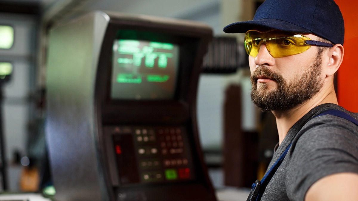
G-code is the language spoken by virtually every numerically controlled machine tool, from a milling machine in a small workshop to a machining centre on a factory floor. In this guide you will find G-code explained from the ground up: where it came from, how a program is structured, what the essential G commands do, what the machine zero point is and how G-code is generated in practice. At the end we take a sample CNC program apart line by line.
What G-code is
G-code is the standard programming language for numerically controlled machines, used to write the commands that control tool movement and machine functions. Its formal foundations are two standards: the international ISO 6983 and the German DIN 66025, which define the common core shared by most controls.
The name comes from the letter G that starts the most important commands, although a complete CNC program also contains the addresses M, X, Y, Z, F, S and T. The roots go back to the 1950s and the American RS-274 standard; today every control manufacturer, Fanuc, Siemens, Heidenhain or the open-source LinuxCNC, has its own dialect, but the core remains shared. Among CNC programming languages G-code is what English is among natural languages: if you know it, you can talk to almost any machine.
The purpose of G-code is simple: to turn the geometry from a technical drawing into planned tool movements plus commands for the spindle, coolant and tool magazine. CNC machining (Computer Numerical Control) means precisely that the machine is controlled by a program rather than by hand-cranked wheels. This makes metal cutting repeatable: once written, a program runs identically the first time and the thousandth time, which is the foundation of what we call precision manufacturing.
How CNC programming works
CNC programming is the process of translating part geometry into instructions the controller understands. A CNC machine operates in a simple cycle: the controller reads the G-code file block by block, interprets the commands and turns them into pulses for the axis drives and the spindle.
Programming tool movements comes down to describing where the tool should go, how fast and along what trajectory, while servo drives execute the motion with an accuracy of thousandths of a millimetre.
The typical workflow looks like this: the designer supplies a model or drawing, the process engineer plans the operations and cutting tools, then a program is written that captures the successive tool movements and machine functions. After simulation and setup the program goes to the machine and the operator supervises the first part. Operating CNC machines does not require writing programs from scratch for every part, but reading and correcting G-code is a core skill at the machine.
G-code structure: block, line and word
A CNC program is a plain text file with a simple hierarchical structure. Each line of G-code, called a block, describes one step: a movement, a machine function or a change of settings. A block consists of words, and each word is an address (a letter) plus a numeric value.
An instruction such as N30 G01 X50.0 Y20.0 F200 means: block number 30, straight-line cutting move to the point X=50, Y=20, at a feed rate of 200 mm/min.
Interpreting G-code commands
Knowing the addresses makes G-code easy to interpret. G selects the type of movement or operating mode, M switches machine functions, X, Y and Z give coordinates, F sets the feed rate, S sets the spindle speed, T selects the tool and N numbers the blocks. Modality matters: most G commands stay active until another command from the same group cancels them. After a single G01, subsequent blocks may contain nothing but coordinates and the controller keeps performing linear moves. That is why real programs look so economical: a mode declared once holds for dozens of blocks.
The coordinate system and the machine zero point
Every program coordinate is measured from a zero. The machine zero point is a fixed reference established by the manufacturer, usually at the end of axis travel; it is from this point that the machine builds its coordinate system after every start-up and homing move (G28 is the return to the reference position tied to machine zero).
The workpiece zero point, in turn, is the zero from which the part dimensions are conveniently measured, for example a corner or the axis of a bore.
Because the machine zero point lies far from the clamped part, in practice a zero offset is used: commands G54 to G59 store in the controller the distance between machine zero and workpiece zero, measured with a probe or an indicator during setup. The programmer then writes coordinates relative to the part and the controller adds the offset from machine zero itself. G53 temporarily switches back to machine coordinates, for example to reach a safe tool-change position, while the older G92 sets the zero programmatically, without the offset table. On top of this come two dimensioning modes: G90 (absolute coordinates, measured from the active zero) and G91 (incremental, measured from the current position). Mistakes around zero are the classic machine-shop accident: a wrongly entered zero offset, or machine zero confused with workpiece zero, ends in scrap or a crash, which is why program settings are always verified before the start.
Essential G commands: tool movements
Four movement commands are the absolute base every course starts with. G00 is the rapid move: positioning the tool at the machine's maximum speed, clear of the material. G01 is a linear move at the programmed feed, i.e. the actual cutting move in the material.
G02 and G03 are circular interpolation, clockwise and counter-clockwise; these moves let you mill arcs and circles without any extra maths on the operator's side. G04, a programmed dwell, completes the set, used for example at the bottom of a bore to improve its surface.
It is worth knowing that rarer codes from this family exist too: G05 and G06 appear in high-speed machining and spline interpolation, G07 with virtual axes, and G09 forces an exact stop in a corner. These, however, are specifics of a particular control and machine type.
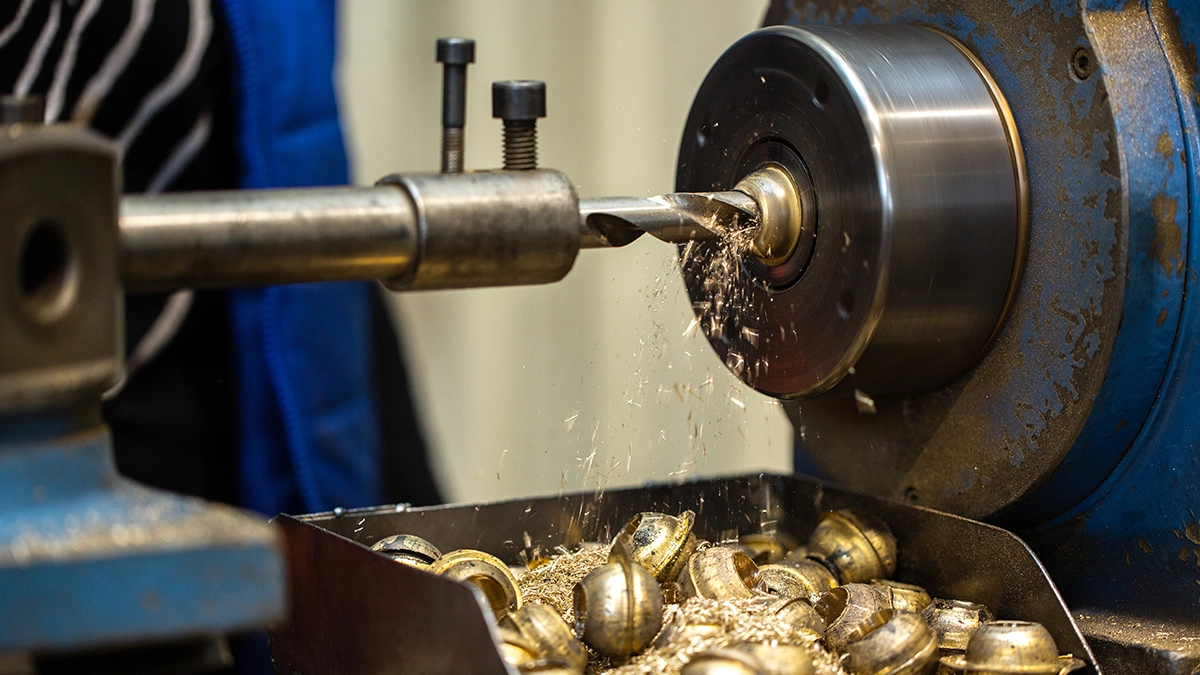
CNC G-codes: an overview of the most important commands
The most important G-codes fall into a few groups: moves and dwell (G00-G04, G09), units and dimensioning mode (G20/G21, G90/G91), zeros and coordinates (G28, G53, G54-G59, G92), tool compensation (G40-G43), canned cycles for holes and threads (G76-G87, cancelled by G80, return level G98/G99) and feed and speed modes (G94-G97).
The table below collects the G-codes you will meet in most programs. Treat it as a cheat sheet consistent with ISO 6983 / DIN 66025; descriptions may differ slightly between controls.
| Code | Function |
|---|---|
| G00 | rapid move (positioning clear of the material) |
| G01 | linear move at cutting feed |
| G02 / G03 | circular interpolation CW / CCW |
| G04 | dwell |
| G09 | exact stop in the block |
| G20 / G21 | dimensions in inches / millimetres |
| G28 | return to the machine reference point |
| G33 | thread cutting with feed synchronised to spindle speed |
| G40 / G41 / G42 | cancel / left / right tool radius compensation |
| G43 | tool length compensation |
| G53 | machine coordinates (from machine zero) |
| G54-G59 | workpiece zero offsets |
| G76 | fine boring cycle (mills) / threading cycle (lathes) |
| G79 | parametric machining cycle (selected controls) |
| G80 | cancel canned cycles |
| G81 / G82 / G83 | drilling cycle: simple / with dwell / peck drilling |
| G84 | tapping cycle |
| G87 | back boring cycle |
| G90 / G91 | absolute / incremental dimensioning |
| G92 | programmatic zero point setting |
| G94 / G95 | feed in mm/min / mm/rev |
| G96 / G97 | constant surface speed / constant spindle speed |
| G98 / G99 | cycle return to initial / retract plane |
Tool radius and length compensation
G41 and G42 shift the toolpath by the cutter radius, so you program the part contour rather than the tool centre; G40 cancels the compensation. G43 adds length compensation taken from the tool table. Thanks to these, editing a program after a cutter regrind comes down to correcting one value in the table without touching the code.
Drilling and tapping cycles
A drilling cycle is a ready-made sequence, approach, drill, retract, packed into a single block. G81 is enough for shallow holes, G82 adds a dwell at the bottom, and G83 retracts the drill every few millimetres to break the chip in deep holes. G84 is rigid tapping, where the controller couples spindle rotation to the feed, much like G33 does for thread cutting on a lathe. G98 and G99 decide the height the tool returns to between holes, and G80 ends the cycle.
Units, feed and spindle speed
G20 and G21 switch between inches and millimetres, as every program downloaded from the internet in the wrong units painfully reminds us. G94 and G95 define whether the feed is per minute or per revolution, while G96 and G97 are lathe territory: constant surface speed maintains surface quality on a changing diameter by adjusting the spindle speed on the fly.
M-code: the machine functions
The other half of the language is M-code: commands that switch machine functions unrelated to geometry. The most important are M03 and M04 (spindle start clockwise and counter-clockwise), M05 (spindle stop), M06 (tool change), M08 and M09 (coolant) and M30, the end of program with rewind.
Modern CNC machines include tool magazines, so tool changes happen automatically: the block T05 M06 loads tool number 5 with no operator involved. It is precisely the automatic tool change that lets one program drill, mill and tap in a single setup.
A sample G-code program explained line by line
The sample program below has 17 blocks: it sets millimetres, absolute dimensioning and the G54 zero, runs a 10 mm end mill around a rectangle at a depth of 2 mm, then changes to a 6 mm drill, drills one hole with the G81 cycle to -12 mm and ends with M30.
Here is a simple milling program: a contour pass around a rectangle and one drilled hole.
%
O0006 (PLATE 60x40)
N10 G21 G90 G54          (millimetres, absolute dimensioning, work zero G54)
N20 T01 M06              (tool change: 10 mm end mill)
N30 S3000 M03            (spindle 3000 rpm, clockwise)
N40 G00 X-10.0 Y-10.0 Z5.0  (rapid move above the start point)
N50 G01 Z-2.0 F100       (plunge to 2 mm depth, cutting feed)
N60 G01 X70.0 F300       (linear move along the bottom edge)
N70 G01 Y50.0            (right side - G01 still active)
N80 G01 X-10.0           (top edge)
N90 G01 Y-10.0           (back to start)
N100 G00 Z50.0           (safe retract)
N110 T02 M06             (tool change: 6 mm drill)
N120 S1500 M03           (new spindle speed)
N130 G00 X30.0 Y20.0     (positioning above the hole)
N140 G81 Z-12.0 R2.0 F80 (drilling cycle to -12 mm)
N150 G80 G00 Z50.0       (cancel cycle, retract)
N160 M05 M09             (spindle and coolant stop)
N170 M30                 (end of program)
%
This short script shows everything that matters: settings at the top, tool movements along the contour, a canned cycle and a tidy ending. Controlling the Z-axis moves (safe height first, then the plunge) is the habit that protects both the tool and the part.
Generating G-code: by hand or from CAD/CAM
Simple parts can be programmed by hand at the machine and many operators work this way daily. For complex shapes manual writing makes no sense: G-code generation is taken over by CAD/CAM systems, which plan toolpaths from the 3D model while a postprocessor translates them into the dialect of a specific control.
Simpler tools can generate G-code too: the DraftSight G-Code Generator creates programs straight from a 2D drawing, 3D-printing slicers generate G-code for printers, and the free LinuxCNC lets you run your own machine on an ordinary computer. Whatever the source, generation ends with a text file that can always be polished by hand.
Verifying the NC code
Before a program reaches the machine it is worth checking in a simulator: graphical verification catches collisions, wrong offsets and typos more cheaply than a broken cutter does. Another good practice is a first part at reduced feed with a hand on the override dial. Skipping simulation is acceptable for trivial programs; for everything else those few minutes simply pay off.
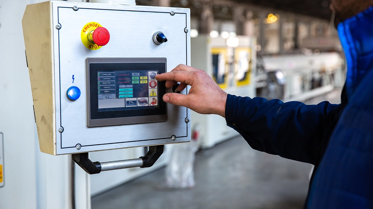
Where you will meet G-code
Although associated with milling, G-code steers motion almost everywhere repeatable machine movement matters. Milling machines and lathes are the classics, but the same language drives laser cutting, plasma cutting, wire and waterjet machines, grinders, boring mills, even industrial robots and 3D printers.
Not all CNC machines understand exactly the same dialect, so when choosing a machine for production it is worth checking the control and the available postprocessor. The application also determines which command groups get used: on a lathe G96 and threading cycles rule, on a cutting table the motion is limited to two axes, and a machining centre uses the full palette.
The potential of CNC machines: optimisation and process automation
A well-written program means more than correct geometry: it also means a shorter cycle time. CNC optimisation starts in the code: shorter G00 paths, a well-thought-out order of operations, fewer unnecessary tool changes and feeds matched to the material can cut cycle time by tens of percent with no investment at all.
The full potential of CNC machines is unlocked by process automation: bar feeders, measuring probes and industrial robots loading parts keep the machine working while the operator does something else. We wrote about why every saved spindle minute is worth so much in our article on the most expensive minute in CNC machining.
From the buyer's perspective it works the same way, only in reverse: the fewer programmer and spindle hours your part needs, the less you pay. In the MetronQ quoting tool part geometry translates directly into machining time, and indicative rates are listed in the pricing section. CAM programming and setup are added once per batch, as described in how the automatic quote is computed. It is also worth remembering that the price is driven not only by the program but also by drawing tolerances and the required surface roughness.
Frequently asked questions about G-code
How does G-code differ from M-code?
G commands describe geometry and motion: where, how fast and along what trajectory the tool travels. M-code controls the machine's devices: spindle, coolant, tool magazine. For example, G01 is a cutting move, while M03 starts the spindle, M06 changes the tool and M30 ends the program. A complete CNC program uses both, interleaved.
Are G-codes the same on a lathe and a milling machine?
Not entirely: the core is shared (G00, G01, G02, G03, G90, G91), but lathes work in the X and Z axes, use G96/G97 and their own turning cycles, while mills have drilling cycles and compensation in the XY plane. A milling program will not run on a lathe without rework.
How does an automatic tool change work?
A block such as T03 M06 tells the machine to return the current tool to the magazine and load tool number 3. The controller applies the length compensation from the tool table (G43), so every tool has a correct zero in the Z axis. This lets one program drill, mill and tap in a single setup.
What sets the spindle speed and the feed?
The S address sets the speed (e.g. S3000) and M03/M04 start it; the F address defines the feed rate, interpreted according to G94 or G95. On lathes G96 maintains a constant surface speed regardless of diameter. G94 means feed per minute, G95 feed per revolution, and G97 returns to a constant spindle speed.
Where should I start to write my first CNC program?
With the four movements (G00, G01, G02, G03), G90/G91 dimensioning and understanding what the machine zero point and the G54 offsets are. Then drilling cycles and radius compensation. Reading a ready program block by block, like the sample above, is good practice. A free simulator or LinuxCNC is enough to practise without access to a machine.
Do I need to know G-code if I have CAD/CAM?
Yes, in practice at least passively. The CAM system will generate the program, but something always needs correcting at the machine: a feed, a zero offset, the order of blocks. An operator who reads G-code catches a postprocessor error before it costs a cutter or a part.
What is program-level CNC optimisation for?
Shortening cycle time and saving tools: fewer empty moves, fewer tool changes, feeds matched to the material. Shorter G00 paths and a well-thought-out order of operations can cut cycle time by tens of percent with no investment at all. In series production even a minor program improvement is multiplied by the number of parts.
Sources
- 1.ISO 6983-1:2009 - Numerical control of machines - Program format and definitions of address words
- 2.DIN 66025 - Struktura programu dla obrabiarek sterowanych numerycznie
- 3.P. Smid, "CNC Programming Handbook", 3rd ed., Industrial Press, 2008
- 4.Dokumentacja LinuxCNC (dialekt RS-274/NGC)
Read next
Automatic CNC machining quotes
Priced from the 3D model or the drawing, on your machines and your rates. You just approve it. 14 days free, no card.
Create a free account