Machining Process Plan: Steps and a Shaft Example
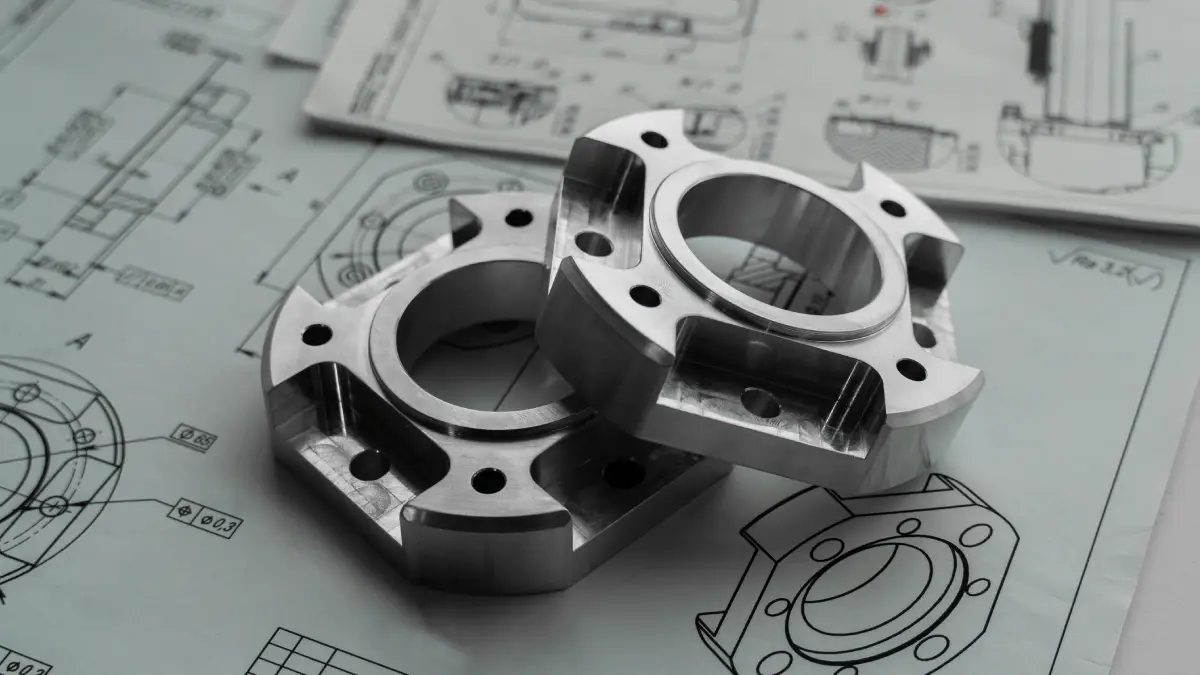
A machining process plan is the part of the production process in which a workpiece changes its shape, dimensions, properties or surface condition, from raw stock to a finished part. It is broken down into operations, setups and work steps, and once written down it tells the shop floor what to do and in which order, and tells the estimator how long it will take.
This guide explains what a machining process plan consists of, how process planning works and what drives its cost. Most of the space goes to a worked example: a stepped shaft in C45 steel (close to AISI 1045) taken operation by operation, with the CNC machines, work steps and times. At the end there is a shorter bushing example and a FAQ.
What a machining process plan is
The process plan covers only the activities that change the workpiece directly: cutting, heat treatment, forming, welding, assembly. Everything around them, such as transport, storage, inspection and production preparation, belongs to the wider production process. The distinction matters in practice: moving a part between work centres does not change it, but it costs the same as machining time, so a process planner tries to keep such gaps to a minimum.
Production process vs. machining process
The production process is everything that turns material into a product ready to ship. Machining is its core, but not the whole of it. In a typical CNC job shop the production process includes:
- production preparation: drawing review, process planning, CNC programs, workholding;
- the machining process itself: sawing, turning, milling, heat treatment, grinding, assembly;
- inspection: in-process measurement and final inspection;
- transport and storage: between the store, the work centres and subcontractors.
Transport between operations has its own equipment. Textbooks usually split conveyors into three groups: conveyors with a traction element, where a belt, chain or rope carries the load; conveyors without a traction element, such as roller, vibrating and screw conveyors; and conveyors that use a carrier medium, where air or liquid moves the material (pneumatic and hydraulic transport). In machine shops the most common are roller conveyors between machines and chain or belt conveyors for chips. None of them changes the part, but their layout decides whether a part waits a minute or two days for the next operation.
Where process planning is used
Every manufacturing field has its own processes: casting, forming, machining, welding, heat treatment, assembly. Machining process plans are used wherever there are machine parts: general machinery, the automotive and aerospace industries, energy and electronics (housings, heat sinks, connectors). In semiconductors the word "process" has a second meaning: a "7 nm process" is the size of the smallest structures on a chip, set by lithography, not a sequence of operations. This article is only about process plans for machined parts.
Structure of a process plan: operation, setup, work step
A process plan is hierarchical. The terms below follow classic process planning textbooks (Feld) and common shop practice, and each one is illustrated with a sentence from the shaft example further down.
| Term | Definition | Shaft example |
|---|---|---|
| Operation | the part of the process done at one work centre, on one part (or batch), without interruption for other work | operation 20: turning side A on a CNC lathe |
| Setup | the part of an operation done with the part clamped once | flipping the shaft to the other end is a new setup and a new setup time |
| Clamping | holding the part after it has been located relative to the machine | shaft located on diameter and face, gripped in a three-jaw chuck |
| Position | part of a setup with the same clamping, but the part in a different position relative to the tool | indexing the spindle 180° on a CNC turning centre before milling the second flat |
| Work step | part of an operation done with one tool, on one surface, at constant cutting data | rough turning the Ø35 journal with a CNMG insert |
| Pass | part of a work step in which the tool removes one layer of material | one pass at a depth of cut mm |
Locating and clamping are often confused. Locating removes the part's degrees of freedom (what it sits on and what it rests against), while clamping holds that position against the cutting forces. Poor locating causes dimensional errors however hard the part is clamped. Every level of the table has its place in the documents: operations on the process sheet, work steps and passes on the operation sheet and in the program.
The process plan as a tree
The simplest way to draw a process plan is as a tree in which every level sits inside the one above:
process → operation → setup → position → work step → pass
For cost, two levels matter most: the operation, because changing work centre means transport and queueing, and the setup, because every new clamping means setup time, new datums and a new chance of error. Work steps and passes determine the machining time. The process sheet records the process at operation level, and the operation sheet breaks a single operation down into work steps.
Process planning in machining: the steps
Process planning is done by a process planner who knows the drawing, the machines in the shop and the batch size. The planner does not change the drawing but has to understand the design requirements behind its tolerances and surface finishes. The steps follow the same order in textbooks and in shops, because each one uses the results of the previous one:
- Drawing and requirements review. Material, dimensional tolerances, surface finish, geometric tolerances, heat treatment. This is where the critical surfaces show up, together with their cost: tight tolerances can double machining time (how tolerances affect machining cost).
- Stock selection. Bar, forging, casting or plate, always with a machining allowance. Small shaft batches come from bar; large ones from closed-die forgings that save material and roughing time.
- Datum selection. The surfaces the part is located on and measured from. For shafts the classic datum is a pair of centre holes, because they let every operation return to the same axis.
- Operation sequence. Preparatory machining first, then roughing, semi-finishing and finally finishing. Heat treatment goes before the operations that must remove its distortion.
- Machines and tooling. Which CNC machines, which workholding, fixtures and tools.
- Cutting data. Speed, feed and depth of cut for each work step, from the tool catalogue or the cutting parameters calculator.
- Time standards. Setup time per batch and unit time per piece for every operation.
- Documentation. The process recorded on process sheets, operation sheets and CNC programs.
Process planning does not end on paper. After the first batch the planner compares the standards with reality and corrects the plan, which is the simplest form of process optimisation in a small shop.
Machining stages: from preparatory work to finishing
Machining stages are defined by their purpose, not by the machine. Preparatory machining (sawing, facing, centre drilling) prepares the stock and the datums. Roughing removes most of the allowance at large depths of cut and feeds. Semi-finishing brings the part close to size and leaves an even allowance. Finishing gives final size and surface finish, and where turning is not enough, abrasive processes take over: grinding, lapping, honing. Surface roughness shows the boundary well: CNC turning and milling typically give µm, careful finish turning µm, and below that you usually have to grind. The last stage is covered in our article on finish machining.
Choosing a CNC machine for each operation
Machine selection starts with geometry and batch size. Shafts and bushings go to CNC lathes, flat and prismatic parts to CNC machining centres, and parts that need both to turning centres with driven tools. When choosing a machine, the planner looks at the diameter and length range, spindle power, number of axes, accuracy and whether there is a sub-spindle for the second side. The CNC control, with its drives and position feedback, determines positioning accuracy and which machining cycles are available. Newer CNC machines with a touch probe measure the part and correct tool offsets themselves, which changes the process: some measurements stop being a separate operation. Older machines without a probe need manual measurement, which has to be included in handling time.
The CNC program: CAD/CAM and G-code
Every operation on a CNC machine has its own program. For simple turned contours the operator writes it by hand at the machine; manual G-code is enough for facing, turning steps and chamfers. Complex shapes are programmed in CAD/CAM: a 3D model from CAD, toolpaths in CAM, code from the post-processor. CAM shortens programming time but does not remove the need to read the code, because corrections are made at the machine. G-code is covered in our G-code programming guide, and CAD/CAM packages in our overview of CNC software. The CNC program is part of the process documentation just like the process sheet.
Time standards: setup time and unit time
Every operation has two kinds of time. Setup time is incurred once per batch: setting up the fixture, changing jaws, loading the program, machining and measuring the first part. Unit time is incurred for every piece:
where:
- - machining time, while the tool is removing material [min],
- - handling time: clamping, rapid moves, tool changes, measuring [min],
- - allowances for workplace servicing and personal needs [min].
The machining time of a single turning pass follows from tool path, spindle speed and feed:
where:
- - tool path including approach and overrun [mm],
- - spindle speed [rpm],
- - feed [mm/rev].
The time standard for a whole batch of pieces is . This explains most of the price difference between small and large batches, as the numbers below show.
Machining process plan example: a stepped shaft
The clearest way to see a process plan at work is a real part. Take a stepped shaft, a typical gearbox or drive component, and follow it from bar stock to final inspection.
Drawing and requirements
The shaft is 180 mm long and has five steps, counting from side A:
- a Ø30 h7 journal, 45 mm long, with an 8 N9 keyway for an 8 × 7 parallel key;
- a Ø35 h6 bearing journal, 20 mm long, µm;
- a Ø42 collar, 70 mm long;
- a second Ø35 h6 bearing journal, 20 mm long, µm;
- a Ø32 end journal, 25 mm long.
The drawing carries the design requirements of the machine the shaft will work in: the designer specified h6 journals for 6207 ball bearings and an h7 journal for a keyed coupling. The material is C45 steel, quenched and tempered, batch size . All other surfaces are µm, and the radial runout of the bearing journals relative to their common axis must not exceed 0.01 mm. Under ISO 286-2, h6 at Ø35 is 0/-16 µm and h7 at Ø30 is 0/-21 µm (Ø30 belongs to the range above 18 up to and including 30 mm). The h6 tolerance together with is what forces grinding of the bearing journals, because turning in a batch cannot reliably hold IT6 at that finish. The h7 journal can still be finish-turned carefully.
Stock and datums
The stock is hot-rolled C45 bar, Ø45, sawn to 185 mm. A 5 mm length allowance is enough to face both ends, and 1.5 mm per side on the Ø42 collar removes the rolled skin. At 50 pieces a forging makes no sense: the die cost would never pay back on such a small quantity.
The datums are the centre holes made in the first two turning operations. From operation 50 onwards the shaft is machined between centres, so every finished and ground diameter shares the same axis. This is the principle of datum consistency: if every finishing operation uses the same centre holes, journal runout depends on the machine, not on repeated re-clamping.
Operations: the shaft process plan in a table
| No. | Operation | Machine | Scope | [min] | [min] |
|---|---|---|---|---|---|
| 10 | Sawing | band saw | Ø45 bar to 185 mm | 10 | 2.5 |
| 20 | Turning, setup I | CNC lathe | face side A, centre drill, rough the Ø30 and Ø35 journals and half the collar | 45 | 4.0 |
| 30 | Turning, setup II | CNC lathe | flip into soft jaws, face to 180 mm, centre drill, rough side B | 20 | 3.5 |
| 40 | Quench and temper | subcontractor | to approx. 220-260 HB | - | - |
| 50 | Finish turning | CNC lathe, between centres | all diameters to size, Ø35 journals with 0.3 mm grinding allowance, chamfers, relief grooves | 30 | 3.0 |
| 60 | Keyway milling | CNC machining centre | 8 N9 keyway on the Ø30 journal, Ø8 end mill, shaft in V-blocks | 30 | 2.0 |
| 70 | Journal grinding | CNC cylindrical grinder | two Ø35 h6 journals, µm, between centres | 40 | 4.0 |
| 80 | Deburring and inspection | inspection bench | diameters, runout, surface roughness | 10 | 3.0 |
| Total | 185 | 22.0 |
The times are standards for a small shop with manual loading and in-machine measurement. In a shop with automatic loading and a touch probe, the turning unit times would be shorter, but setup times would hardly change.
Operation 20 broken down into work steps and passes
Operation 20 shows the difference between operation, setup and work step well. It is one operation on one CNC lathe in one setup: the bar gripped in a three-jaw chuck with about 100 mm stick-out. It consists of five work steps:
- Face side A with a roughing tool, one pass, 2.5 mm off the length.
- Centre drill with an A3.15 centre drill, one pass.
- Rough turn the Ø30 journal with a CNMG insert, from Ø45 to Ø31.
- Rough turn the Ø35 journal with the same tool, to Ø36.
- Rough turn half of the collar to Ø43.
Steps 3-5 are done by the same tool in one program cycle, but each surface is a separate work step. At mm, going from Ø45 to Ø31 takes three passes, and all three belong to the same work step.
Roughing data for normalised C45: m/min, mm/rev, mm. About 54 cm³ of material comes off side A, and the machining time itself is under a minute. The rest of the 4-minute unit time is handling and allowances: clamping, rapid moves, tool changes, checking the first steps.
Operation 50 looks similar. Finish turning the Ø35.3 journal, 20 mm long, with approach mm, at m/min ( rpm) and mm/rev takes:
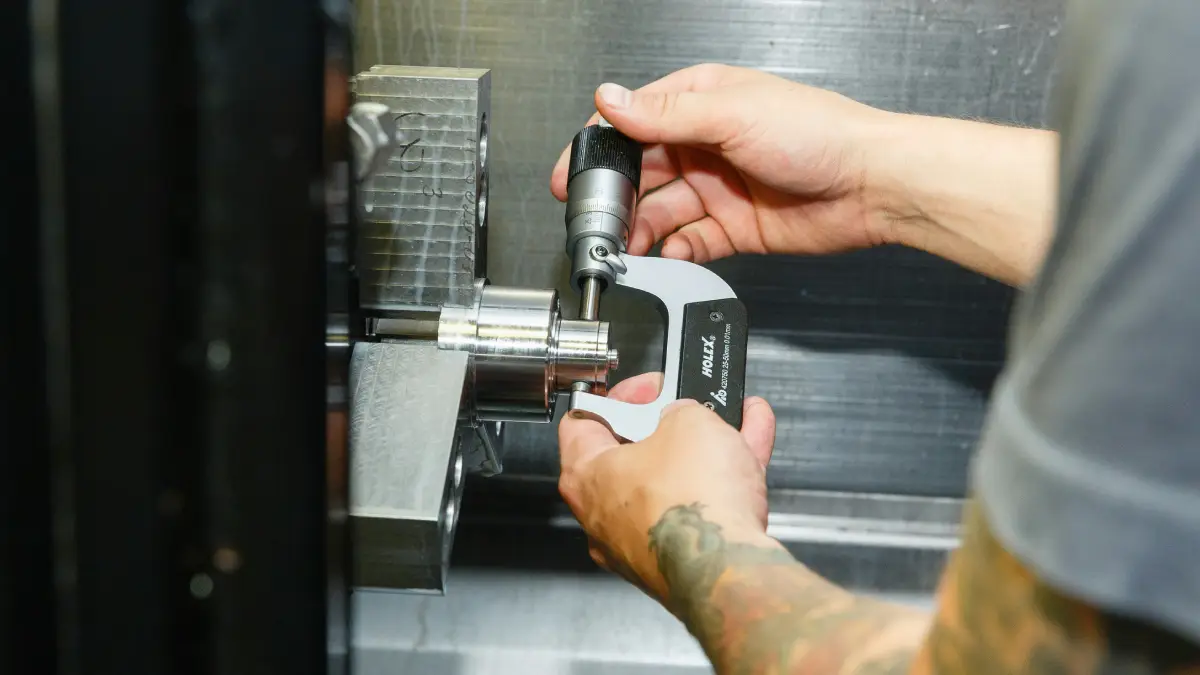
About six seconds. The whole finishing contour of the shaft is just over a minute of machining time, and the rest of the unit time is mounting between centres with a face driver, measuring with a micrometer and changing tools. That is why cutting handling time pays off more in small batches than pushing cutting data. How turning steps are machined and what drives journal surface finish is covered in our guide to longitudinal turning.
Why this operation sequence
The sequence is not arbitrary. Roughing before heat treatment removes most of the material while the steel is soft and easy to cut. Quenching and tempering after roughing treats a part with a small allowance, so the section hardens more evenly, and finish turning removes the heat-treatment distortion. The keyway is milled after finish turning, because interrupted cutting over a keyway spoils the surface and the insert life. Grinding is the last shaping operation, because nothing afterwards may touch the h6 journals. Final inspection checks everything the drawing marks as critical.
This shaft process plan is written down in a document that the shop floor receives together with the drawing. The same shaft as a process sheet, with fields to fill in and a free XLSX template, is shown in a separate article.
Bushing process plan: a short example
A bushing illustrates a different rule: whatever must be concentric is machined in one clamping. Take a C45 bushing Ø50 × Ø30 H7 × 40 mm with 0.02 mm concentricity between bore and outside diameter, batch of 100.
| No. | Operation | Machine | Scope |
|---|---|---|---|
| 10 | Turning from bar, setup I | CNC lathe with bar feeder | face, turn Ø50, drill Ø28, bore Ø30 H7, chamfers, part off at 40.5 mm |
| 20 | Turning, setup II | CNC lathe | grip on Ø50 in soft jaws, face to 40 mm, chamfers |
| 30 | Deburring and inspection | inspection bench | bore with a plug gauge, concentricity on a mandrel |
Operation 10 is the key: outside diameter and bore are machined one after the other in the same clamping, so their concentricity depends only on the lathe. Boring in a second setup would add the re-clamping error straight into the 0.02 mm tolerance. On a CNC lathe with a sub-spindle, operation 20 disappears because the second spindle picks up the part and faces the other end in the same cycle. That is what a bushing process looks like in series production: fewer operations, fewer setups, a shorter route through the shop.
Process control: getting high-quality results every time
A good process gives a good first part. Process quality, however, is measured by whether the fiftieth part matches the first. Product quality follows directly from process quality, which is why ISO 9001 clause 8.5.1 requires production under controlled conditions: documented information, suitable equipment, monitoring and validation of processes whose output cannot be fully verified afterwards.
In a machine shop process control rests on a few elements:
- first-article inspection after every setup, before the batch runs;
- in-process measurement built into the plan, for example journal diameters before grinding;
- statistical process control (SPC): control charts for critical dimensions and capability indices and ;
- final inspection to an inspection plan, with recorded results.
Process control works on two levels. On CNC machines it means touch probes, tool measurement and spindle load monitoring that detects a broken insert. At shop level, production monitoring systems collect measurements and times from many work centres, so process control no longer depends on operators' notes. Even the best monitoring does not replace a well-designed process: if the datums are wrong, a control chart will only show that the process is consistently wrong.
The capability index shows how many times the process spread fits into the tolerance, taking the shift of the mean into account:
where:
- , - upper and lower specification limits [mm],
- - mean of the measurements [mm],
- - process standard deviation [mm].
Automotive customers usually require for critical dimensions. The automotive industry has the most formal process control, and it introduced most of the tools that small machine shops use today. A process at produces high-quality results by design, not by luck.
What a process plan costs: the number of setups
A written process plan is a ready-made time estimate. With setup time, unit time and a machine hour rate, the machining cost per piece is:
where:
- - machining cost per piece,
- - total unit time of all operations [min],
- - total setup time [min],
- - machine hour rate converted to a rate per minute,
- - number of pieces in the batch.
For the shaft above, at a simplified shared rate of 180 per hour (3 per minute):
| Batch | Cost per piece | ||
|---|---|---|---|
| 50 pcs | 66 | 11 | 77 |
| 5 pcs | 66 | 111 | 177 |
At five pieces, setups cost more than the machining itself. Every setup adds its own setup time, so the number of setups is the biggest cost lever in small batches. On a CNC turning centre with a sub-spindle and driven tools, operations 20 and 30 merge into one because the second spindle takes over the shaft, and the keyway is milled in operation 50 without moving to a milling machine. The process loses two operations: setup time drops from 185 to about 145 minutes and unit time from 22 to about 20.5 minutes. At five pieces that saves about 28 per piece, at fifty about 7, and since such a machine has a higher hourly rate, the gain shrinks in large batches. Cost reduction in small batches therefore starts with the number of setups, not with cutting data, and process planning for short runs should start with the same question.
Material with allowance (Ø45 × 185 mm bar is about 2.3 kg of steel) and the heat-treatment subcontract still have to be added to the machining cost.
The process plan decides how many setups a part needs, and setups decide the price of a small batch. MetronQ calculates the setup for every clamping from the 3D model, together with material including allowance and tolerances, and the process planner sees the breakdown and approves the quote. The price and time per operation are shown in the shop panel, and plan details are on the pricing page.
Why process planning matters to industry
The process decides three things at once: quality, cost and delivery. The same drawing made with two different processes can cost twice as much and produce twice as many rejects, because process quality depends on datums, sequence and the number of re-clampings. That is why good process planning matters in every industry: machine building, aerospace and electronics all rely on the same rules for datums, sequencing and time standards.
Process optimisation today is mainly about combining operations: mill-turn centres that finish a keyed shaft in one clamping, automation that loads parts into CNC machines, and in-cycle measurement. Advanced processes such as complete machining on multi-axis machines or hard turning instead of grinding remove entire operations from the route. The automotive industry adopts them fastest, because in large batches every second of unit time has a price. In a small shop optimisation starts more simply: with one current version of the process that the planner, the shop floor and the ERP system all see, and with process control based on measurements rather than an operator's memory.
Frequently asked questions about machining process plans
What is a machining process plan?
It is the part of the production process in which the workpiece changes its shape, dimensions, properties or surface condition. Transport, storage and inspection do not change the part, so they belong to the wider production process. It consists of operations, setups, work steps and passes, and it specifies the sequence, machines, tools and times.
What is the difference between an operation and a work step?
An operation is everything done at one work centre without interruption for other work. A work step is the part of an operation done with one tool, on one surface, at constant cutting data. Turning side A of the shaft is one operation; facing, centre drilling and rough turning each step are separate work steps within it.
How do you write a process plan for a machined part?
Start by reviewing the drawing and requirements. Then choose the stock and datums, set the sequence from preparatory machining to finishing, assign machines and tools, select cutting data and set the setup and unit times. Finally, document the process and verify it on the first batch.
What does a shaft process plan look like?
For a stepped C45 shaft with Ø35 h6 journals: saw the bar, rough turn in two setups with centre holes, quench and temper, finish turn between centres, mill the keyway, grind the journals and inspect. The full table with times is above.
What documentation does a process plan need?
The core is the process sheet with operations and times. On top of that come operation sheets for complex operations, CNC programs, an inspection plan and the detail drawing that all documents refer to. Operations go on the process sheet, while work steps and passes go on the operation sheet and into the CNC program.
Why is process planning so important in manufacturing?
Because quality, cost and delivery all depend on it. The number of setups and operations sets the price of a small batch, and process stability sets the reject rate in a large one. In every industry that makes machine parts, a good process is cheaper than fixing a bad one.
Sources
- 1.M. Feld, "Podstawy projektowania procesów technologicznych typowych części maszyn", WNT, 2018 (process structure, datums, shaft and bushing processes)
- 2.R. Wołk, "Normowanie czasu pracy na obrabiarkach", WNT, 1972 (setup and unit time standards)
- 3.J. Grzesik, "Podstawy skrawania materiałów konstrukcyjnych", WNT, 2010 (turning cutting data and machining time)
- 4.Sandvik Coromant, "Training Handbook: Metal Cutting Technology" (cutting data for steels)
- 5.ISO 286-2:2010 (h6, h7 and N9 deviations)
- 6.DIN 6885-1 (parallel keys and keyways)
- 7.D. C. Montgomery, "Introduction to Statistical Quality Control", Wiley (Cp and Cpk indices)
- 8.ISO 9001:2015, clause 8.5.1 (control of production)
Read next
Automatic CNC machining quotes
Priced from the 3D model or the drawing, on your machines and your rates. You just approve it. 14 days free, no card.
Create a free account