Guide
CNC Software: A Guide to CAD, CAM and Control Programs
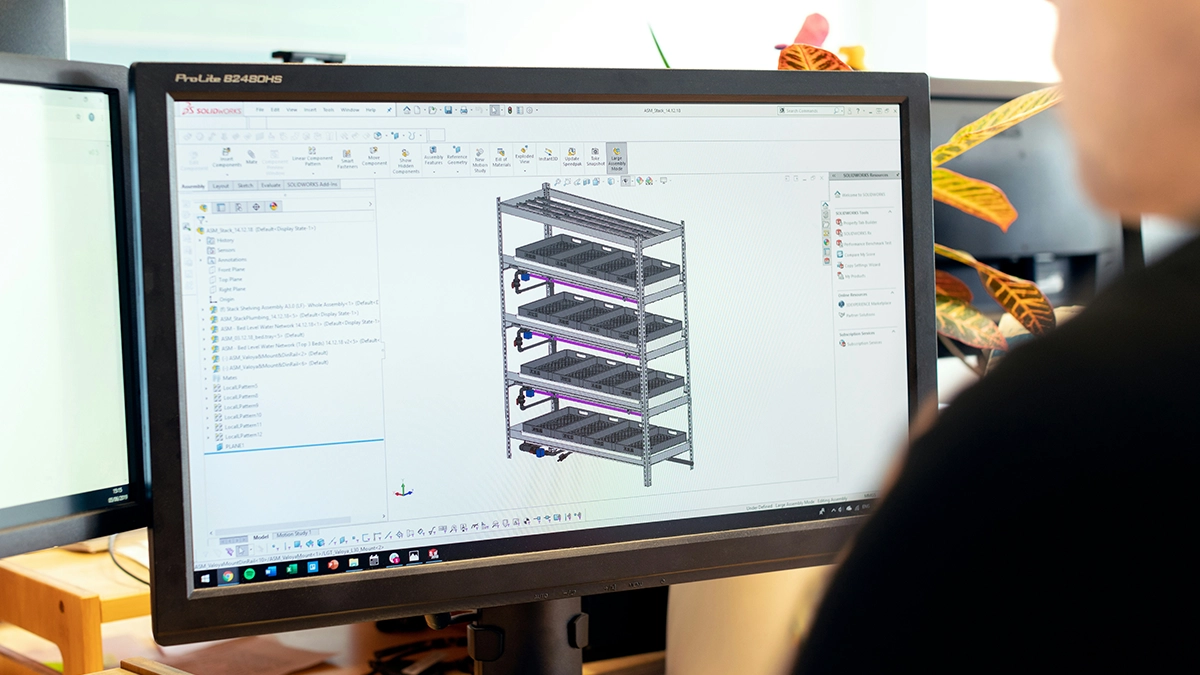
Behind every part that comes off a milling machine stand at least three programs: one in which the design was made, one that turned it into toolpaths, and one that guided the machine. This guide sorts CNC software by role - CAD, CAM and control software - with a review of specific tools, from free to industrial, and advice on matching the software to your machine and budget.
CNC programs and CNC software: three layers
"CNC software" covers three kinds of tools that are easy to confuse. CAD software (Computer Aided Design) is for designing the model or drawing of the part. CAM software (Computer Aided Manufacturing) turns the design into technology: machining plans and toolpaths. Control software runs on the machine tool and turns the machining program into axis motion.
Add simulators, postprocessors and utilities - but the skeleton of every workshop is these three layers, and together they make up the complete software stack of a CNC machine.
This division immediately organises the choice: a designer buys one thing, a process engineer another, and a hobbyist building a CNC router in the garage yet another. The CNC machining process runs through all the layers in order: CAD design, toolpath creation in CAM, execution on the control - and without any one layer the process simply does not close. The language in which the result of this chain is written, i.e. G-code CNC programming, we covered in a separate article - here we deal with the programs, not the syntax.
CAD software for design
CAD software is used to create the model or drawing of a part and is the starting point: without a model or drawing there is nothing to machine. CAD systems divide into 2D (flat drawings, sufficient for plasma, laser or simple milling) and 3D (solid models for the full machining process).
A design program for CNC does not have to be a monster: sheet cutting needs only a clean 2D drawing, and only moulds and multi-axis parts require a solid modeller. An advanced CAD program offers parametric modelling, assemblies and drawing sheets - that is what a design office picks. Comprehensive CAD software carries a project from sketch to documentation; dedicated CAD for a specific industry (sheet metal, furniture, moulds) adds specialised functions, and CAD dedicated to machining adds draft and wall-thickness analysis. CAD systems also differ in philosophy - direct modelling versus history-based - and which wins depends on how often you edit other people's models. The CAD functions that genuinely matter for machining are clean export (STEP, DXF), dimensioning with tolerances and geometry checking; the rest is often garnish. The design process ends with a file the CAM layer will take over, so CAD for a workshop is judged mainly by how smoothly it hands the geometry on.
Free or paid CAD software
Free CAD software goes surprisingly far: FreeCAD handles solid modelling, LibreCAD and QCAD handle 2D drawings, and educational or hobby licences of commercial packages cover home use. Free CAD has its limits, though: large assemblies, repairing imported geometry, formats demanded by corporate customers. Paid CAD software is bought for exactly those reasons - plus technical support with a real SLA. The best CAD software is not the one with the longest feature list but the one that gets you to a correct part fastest; in rankings the giants win, but in a workshop the best CAD is often the mid-range. Treat free CAD as a full candidate, not a crutch - what you get free today is more than licences costing thousands offered a decade ago.
A trial CAD program before you buy
Almost every vendor offers a 14-30 day trial, and that is the moment for verification: open your own ugliest customer files in it, not the tutorial models. The trial will also show whether the functions you are paying extra for are ever used in your work. The same rule applies one layer up: a CAM trial version lets you check the postprocessor on your own machine, and educational CAM versions are often free and sufficient for learning.
CAM software on the way to a CNC program
CAM software is the middle layer on the way from a model to a CNC program: it lays operations, tools and strategies over the CAD geometry, computes the toolpaths, checks them in simulation and, through the postprocessor, writes a finished CNC program for a specific control. Without this layer, the program is written by hand or at the machine.
For simple parts it is a choice, not a necessity: a shaft or a plate with holes is faster to program on the control. With 3D contours, multi-axis machining and repeating series, a CAM system pays for itself quickly, because the machine does not stand idle while the program is being written. How the individual systems work, how SolidCAM, Mastercam and hyperMILL differ, and how to choose a package is covered in our separate guide to CAM software.
A review of programs for CNC machines
The programs for CNC machines reviewed below were chosen to cover the whole ladder, from free hobby tools to industrial systems. Prices and versions change, so treat them as orientation - and almost every one of them has a free trial version.
Mach3 and Mach4
Mach3 is the legend of hobby CNC: control software that turns a PC into a CNC machine control for a mill, lathe or plasma. Despite its age, Mach 3 still drives thousands of machines, because it is cheap, well documented and has a huge community - and this class of control software can be configured single-handedly in an evening. Mach4 is the successor: a rebuilt core, motion controllers over USB and Ethernet, better macro support - Mach4 is the pick for new builds, Mach 3 is what you meet in machines already running. ArtSoft used to bundle LazyCam - a simple importer that made a machining program from a DXF without a full CAM; LazyCam is still enough for simple contours, though today SheetCAM or a free CAM module more often takes its place.
simCNC
simCNC is the Polish answer to Mach3: control software developed by CS-Lab of Kraków, designed for their CSMIO motion controllers. simCNC emphasises trajectory smoothness (S-curve algorithms), stability and Python scripting instead of macros; for anyone building a CNC router or mill on a CSMIO controller, simCNC is the natural choice, and documentation plus technical support in Polish is an argument foreign packages cannot beat. In the Mach3 versus simCNC match-up, the latter wins on modernity, the former on price and the library of ready-made solutions - though in new builds simCNC is steadily eating the market.
SprutCAM X
SprutCAM X is a fully-fledged industrial-class system at a mid-class price: milling from 2.5 to simultaneous 5 axes, turning, mill-turn, even robot programming. SprutCAM X - CAM software with virtual machine simulation as standard - shows collisions of fixtures and axis limits before the run, not on the machine. Its licensing also stands out: postprocessors for popular controls are included in the price, which with competitors can be a separate, painful expense. For a workshop entering 5-axis work, SprutCAM X is one of the cheapest sensible tickets in; in "best CAM under a sensible budget" rankings it appears regularly, and its limitation is a smaller training base than the giants have. It is good proof that CAM used in industry does not have to cost six figures.
ZW3D: Lite, Standard and up
ZW3D is a package that gained popularity as an economical bundle of design and technology: a solid-surface modeller plus machining modules in a single project file. ZW3D Lite is the entry into modelling with 2-3-axis machining, ZW3D Standard adds fuller CAM and geometry repair, and the higher versions of ZW3D add HSM and multi-axis machining. ZW3D's strength is the capability-to-price ratio of a perpetual licence: ZW3D CAD CAM is bought once, with no forced subscription. ZW3D Lite is enough for a hobbyist, ZW3D Standard for a small shop, and you can migrate between them without changing environments - the projects grow with the licence. The weakness is a smaller community than around Western packages, so answers come from the distributor rather than a forum; even so, ZW3D regularly makes the shortlist of firms that want one program instead of two, and the ZW3D trial runs a full 30 days.
Mastercam and SmartCAM 2023
Mastercam is, according to CIMdata's rankings, the most widely installed CAM package in the world: complete milling and turning, strong dynamic strategies, a huge base of postprocessors and training. Mastercam's own CAD tools are enough to prepare and fix geometry for machining - they will not replace a full modeller, which is why they are complemented by integrations with external systems. Mastercam is the safe "nobody got fired for buying it" choice - you pay for that certainty in licence and maintenance prices. SmartCAM 2023 represents the old guard: a technology-first approach built on process knowledge and a loyal user base in tool rooms. SmartCAM 2023 is a niche, but a living one - and proof that CAM software written in the 1980s can still be developed today.
Cheap and free software for CNC mills: MeshCAM, eduCAD and others
A truly free CAM system barely exists - but the neighbourhood of zero is densely populated. MeshCAM targets the user who "wants to mill, not study CAM": it loads STL/STEP, proposes operations itself and hands back a finished program in minutes; paid, but cheap and with a long trial. Free CAM comes as modules of bigger packages (2.5D paths in hobby licences), and open source is represented by PyCAM and the CAM workbench (formerly Path) in FreeCAD - free CAM of this class is enough for simple contours and pockets. A separate shelf is education: eduCAD CNC, a simple Polish program for learning to build machining programs, bundled with the N.CAD postprocessor that outputs code for Polish controls - for schools and courses it is often the first contact with the technology layer. All free CAM shares one trait: it saves money at the cost of time, so in production it holds its own only with simple, repetitive parts.
Laser, plasma and CNC router software
2D cutting has its own rules. SheetCAM is the low-budget standard: a plasma and laser CNC program in one, with kerf compensation, tabs and cut ordering in the sheet; it also handles 2.5D milling, so for many machines it is the only CAM needed. Software for milling CNC routers (wood, dibond, plastics) usually pairs a simple CAM with sheet nesting - the VCarve class rules here, and in artistic engraving, for years, ArtCAM® Standard, whose reliefs still circulate in workshops even though Autodesk ended ArtCAM's development in 2018. An advertising CNC router needs no more than a DXF from the design layer - which is why router owners invest in good nesting rather than a solid modeller. The work of a cutting machine differs from a mill in one more way: what counts is sheet utilisation, so router software is judged by nesting quality, not by the number of strategies. A laser program must also manage power and speed in corners, and a plasma program the torch height (THC); a milling router has its own problem - dust extraction and holding thin sheets down. The common denominator: routers, lasers and plasma live in a 2D world where generating the CAM program takes minutes, not hours.
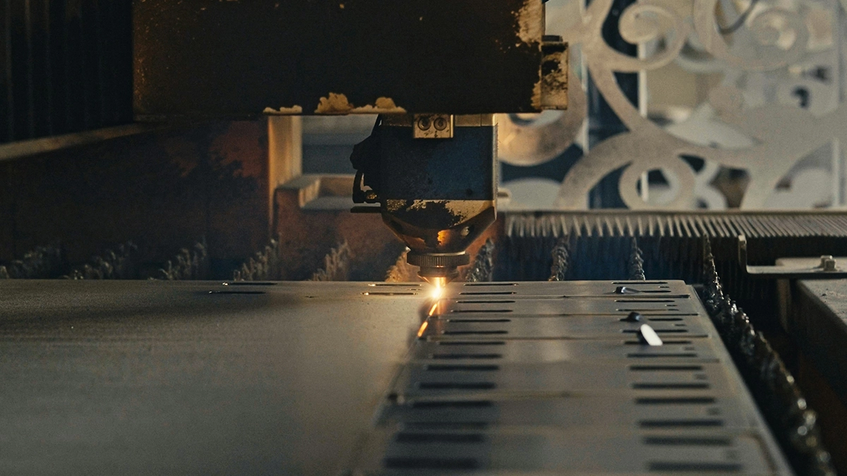
Control software and CNC machine control
The last layer lives on the machine itself - control software in the literal sense. It reads the machining program block by block and turns it into motion: interpolation, compensations, safety. In industrial machines the control software is part of the control.
Fanuc is the world's most popular control and the reference point for postprocessors, Sinumerik (Siemens) dominates Europe and multi-axis milling, Heidenhain with its conversational shop-floor programming is the favourite of tool rooms, and Hurco built its brand on conversational programming at the machine. Machine builders such as DMG Mori or Hermle overlay their own interfaces and cycles on these controls; Haas (often misspelled HASS online) develops a control with syntax close to Fanuc's. Hobby-class control is the Mach3, Mach4 and simCNC described above, plus LinuxCNC and GRBL - the difference from industry lies less in capability and more in certification and reliability. Both worlds' control programs do the same thing: guide the axes along a set trajectory; the industrial class adds diagnostics and service. Control software also ages more slowly than computers - twenty-year-old controls still earn their keep. Day-to-day machine operation happens in this layer: this is where the operator sets offsets, locates the part and supervises the run; and if you pick community-supported control software for your own build, check whether the forum around it is still alive - it is your service department.
The postprocessor: translator between CAM and control
Between the CAM layer and the control stands the postprocessor: it translates neutral toolpaths into the dialect of a specific machine. The same project run through a Fanuc and a Heidenhain postprocessor gives two different files - which is why CAM program generation always ends with the question "for which machine", and why G-code from one machine rarely runs on another without edits. External CAM software is therefore bought together with postprocessors for the controls you own; their availability and price is one of the most important criteria for the whole package.
Programming CNC machines: how a machining program is born
A machining program comes into being one of three ways today. The first is writing CNC programs by hand at the machine - fastest for simple parts and still everyday practice in CNC lathe programming, because a shaft contour is a dozen blocks, well supported by the control's canned cycles.
The second is conversational programming (Heidenhain, Hurco): the operator answers questions about the geometry and the control builds the cycles itself - no syntax knowledge required. The third is the full chain of design, CAM and postprocessor, without which there is no 3D milling and no multi-axis machining: CAM-based CNC programming moves the workload from the machine's keyboard to the engineer's office while the machine cuts the previous part. A 3D milling program over freeform surfaces is CAM territory exclusively - hand-written programs end where curved surfaces begin.
CNC programming and CNC machining in practice
The choice of path is arithmetic, not ideology. Programming at the machine costs machine time (it stands while the operator types), CAM costs a licence and an engineer's seat - the profitability line runs where parts stop being trivial or start repeating. Machine time is the most expensive resource in the shop, so CNC projects prepared offline pay back faster than the software price list suggests; we did that maths in the most expensive minute in CNC machining. Complex machining processes - 5 axes, mill-turn, thin-walled aerospace - have no manual path at all: they are programmed exclusively in CAM, with simulation as the insurance policy on fixtures and spindle. CNC machining itself, from the technology and cost side, is the subject of our guide what CNC machining is; here it is enough to remember that the machining process starts on a screen long before a chip flies off the machine - and a machine waiting for a program is the most expensive form of idleness.
How to choose a CNC program
Start the choice from the end - from the machine and the parts, not from rankings. A CNC program is chosen in four steps. First: what do you cut - 2D sheet, 3-axis milling, turning, 5 axes; that alone crosses out most of the list.
Second: what file do your customers send - DXF needs only a 2D CAM, STEP requires a full system. Third: what control do you have and is a postprocessor available for it - the right CNC software without a postprocessor is a car without wheels. Fourth: budget counted with maintenance, because five years of subscriptions can beat the licence price. A typical shop's milling machines are served by the mid-range; multi-axis machine tools require the upper shelf, and a router the lower one. The right software is the one whose capabilities end a step beyond your needs - not three shelves higher.
Technical support, training and community
With comparable functions, the back-office decides comfort. Technical support in your language, a local distributor who will build a postprocessor for your machine, and available training weigh more than a tenth finishing strategy. CAM used in industry comes with certified training and a knowledge base; CAM used mainly by hobbyists compensates with forums and YouTube - both work, as long as you know which shelf you are reaching for. Check the development cycle too: CAM developed by a small vendor can leave the market together with them - the story of ArtCAM is the warning. Judge the interface on your own parts in the trial version; an interface the engineer dislikes will be avoided regardless of capability. You recognise a good CAM solution by the fact that after a week of testing nobody wants to go back.
Matching software to the machine park
Finally, the rule that ties it together: software for CNC machines is bought to fit the machine park, not the other way round. One CAM solution covering the mills, the lathe and the cutter means one tool library, one training course and one data format; CAM tools scattered across three programs mean three times the friction, and CAM assets - libraries, templates, postprocessors - take years to build. Machines bought later should join the existing chain (another postprocessor), not start a new one. Consistent use of CAM tools in one environment pays one more dividend: tool data parameterised once (feeds, speeds, tool lives) becomes the company's knowledge base. And the business arithmetic for dessert: the software itself earns nothing - the quoted and won part does. CAM shortens production preparation, and instant CNC quoting shortens the road from enquiry to order; software lets you win on reaction time at both ends of the process. What a quoting configurator on the shop's own website changes in that race for orders is covered in winning more CNC orders with online quoting. If quotes need to flow into an ERP or another shop system, that is what MetronQ's API integration is for.
Frequently asked questions about CNC software
Where do I start choosing CNC software?
From the machine and the typical parts: cutting technology, the file format customers send, the control and its available postprocessor - the budget comes last. DXF files need only a 2D CAM, STEP requires a full system, and count the budget with maintenance, because five years of subscriptions can beat the licence price. A ranking without that context says nothing.
How does CAD differ from CAM in CNC programming, and is CAM needed for simple parts?
CAD creates the geometry (model, drawing), CAM turns it into technology: operations, tools, toolpaths and the resulting program. A CAM system is not always necessary: simple turning and drilling are faster to program at the machine or conversationally. It pays for itself with 3D contours, repeating series and wherever simulation protects an expensive part from a mistake.
Is free CAD software enough for CNC machining?
For 2D cutting and simple milling, yes: FreeCAD, QCAD or hobby licences fully cover those needs. The limits appear with large assemblies, repairing imported geometry and customers' formal requirements. Moving to paid CAD software is worth it when working around the gaps costs more than the licence: hours lost on exports, missing required formats, no support during a failure.
How do you write a CNC program without a CAM system?
By hand in G-code or with conversational programming on the control. A simple CNC program for a shaft or a plate with holes is a dozen to a few dozen blocks, and the controls' canned cycles calculate drilling, tapping and pockets for the operator. The manual route ends at curved surfaces and multi-axis machining, where CAM is needed.
Where can I find ready-made CNC programs and examples?
In control programming manuals, in machine documentation and from distributors who include sample CNC programs with their training. A ready-made program must always be checked before it runs: the zero point, tool offsets, speeds and feeds have to match your machine and fixturing, and the code itself the control it was written for.
How much do programs for CNC mills cost?
From zero (hobby and educational versions) through a few hundred euros for simple CNC milling programs (SheetCAM, MeshCAM) and a few thousand for a solid 3-axis package to tens of thousands with annual maintenance for 5 axes. LinuxCNC and GRBL are free on the control side, as is FreeCAD with its CAM workbench.
What CNC router software should I start with?
For a milling router: a simple 2.5D CAM with good nesting (the VCarve class); for laser and plasma, SheetCAM or the tool bundled with the controller. For routers, sheet utilisation and stable work with the driver matter more than the feature count, which is why owners invest in good nesting rather than a solid modeller.
What software is built into CNC machine controls?
A code interpreter, a motion interpolator, tool compensations, canned cycles and, increasingly, conversational programming with simulation. In industry that means Fanuc, Sinumerik, Heidenhain or Hurco - the factory control programs; in hobby machines a computer running Mach4, simCNC or LinuxCNC plays that role. The industrial class adds diagnostics and service on top.
Sources
- 1.vendor documentation: Mach3/Mach4 (machsupport.com), simCNC (CS-Lab, cs-lab.eu), SprutCAM X (sprutcam.com), ZW3D (zwsoft.com), Mastercam (mastercam.com), SheetCAM (sheetcam.com), MeshCAM (grzsoftware.com)
- 2.CIMdata NC Software market reports (CAM market shares)
- 3.LinuxCNC documentation, linuxcnc.org.
Read next
Automatic CNC machining quotes
Priced from the 3D model or the drawing, on your machines and your rates. You just approve it. 14 days free, no card.
Create a free account