Surface Roughness: Ra, Rz, Grades and Tables
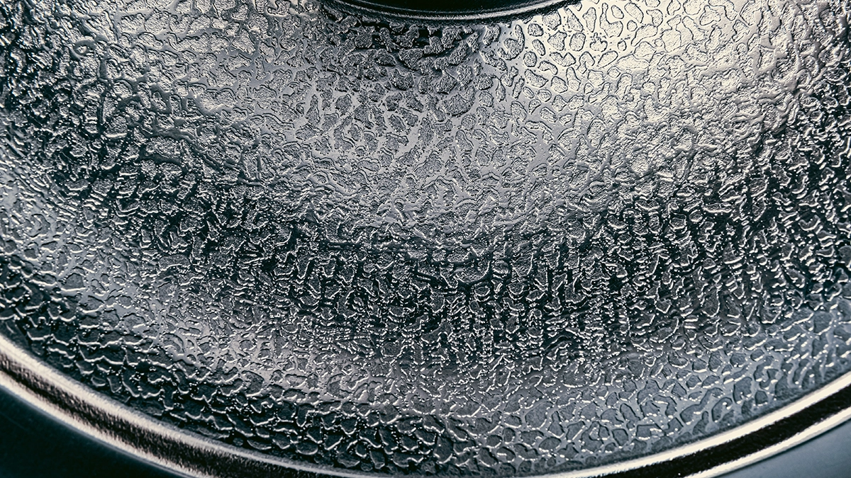
Surface roughness is the set of the finest irregularities left on a surface by a cutting edge or grinding wheel, described in micrometres by the parameters and . It governs friction, sealing and part life, and with them the cost of the part. Below we explain the basic roughness parameters, roughness grades with tables, how Ra relates to Rz and the values machining actually achieves.
What surface roughness and surface texture are
Surface roughness is the finest, closely spaced set of irregularities on a surface: the micro-peaks and valleys left by a cutting edge or by abrasive grains. Together with longer-wave irregularities and form errors they make up the surface texture. Roughness therefore describes only the smallest scale of those irregularities, not the geometry of the whole part.
No machined surface is perfectly smooth. Under a microscope even a mirror finish turns out to be a landscape of peaks and valleys. Roughness depends above all on the process: turning leaves one kind of micro-irregularity, milling another and grinding yet another. That is why roughness is never assessed in isolation from the process plan, and why it comes up on almost every drawing.
Surface roughness affects nearly every function of a part: friction and wear, joint tightness, fatigue strength (the bottoms of micro-valleys act as notches), coating adhesion and corrosion resistance. A rough surface is sometimes wanted, for example for bonding or painting, but on a bearing journal it is a defect. On the other hand, smoothness costs money: the lower the required roughness parameter, the more passes and operations. So we treat roughness like any other dimension: it should be as low as the function requires, and not a bit lower.
Surface structure: roughness, waviness and form errors
Roughness, waviness and form errors are three components of the same measured profile that differ in scale. Roughness is the marks of the cutting edge or wheel, waviness is irregularity with a longer spacing, usually caused by vibration in the machine, fixture, workpiece and tool system, and form errors such as ovality or taper concern the whole geometry.
The surface profile recorded by an instrument is the sum of these three components, so the structure you see on a trace always mixes all three scales. During evaluation they are separated by filters with standardised cut-off wavelengths, and the parameters are calculated only from the extracted roughness profile. EN ISO 4287 calls the unfiltered profile the P-profile, waviness the W-profile and roughness the R-profile.
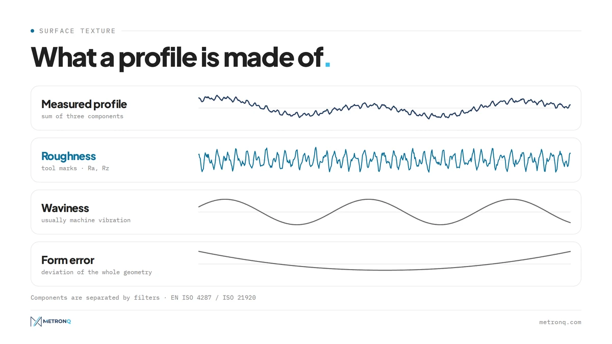
The distinction has practical consequences. Waviness can let a medium through a joint that looked tight on alone, so on sealing faces both components are controlled. Form errors, in turn, are easily mistaken for roughness when parameters are evaluated without a filter. A result without a stated filter and sampling length says little, and a high roughness value in a report may in fact be the effect of vibration.
Typical roughness parameters and units of surface roughness
The basic surface roughness parameters are and , alongside , , and . They are defined in roughness standards: EN ISO 4287, now being replaced by the EN ISO 21920 series, which tidies up the definitions without changing their substance. The units of surface roughness are always the same: micrometres, or microinches in US documentation.
Every parameter value is evaluated over a sampling length, a standardised length of profile: 0.08, 0.25, 0.8, 2.5 or 8 mm. The sampling length is chosen to suit the expected roughness, and the evaluation length is normally five sampling lengths. The part of the R-profile within one sampling length is the basis of every roughness measurement, and without a stated sampling length the results of two laboratories cannot be compared.
For US documentation remember the conversion: 1 µin is 0.0254 µm, so 32 µin is about 0.8 µm and 125 µin about 3.2 µm. The US standard ASME B46.1 defines the parameters much as ISO does and uses the same symbols, so usually only the numbers need converting.
Ra parameter: what Ra means among the roughness parameters
Surface roughness is most often described by the parameter. It is the arithmetic mean of the absolute deviations of the profile from the mean line within a sampling length, commonly called average roughness:
where:
- - ordinate of the roughness profile relative to the mean line [µm],
- - sampling length [mm].
What does mean in practice? The average deviation of the profile from the mean line is 1.6 micrometres. is the most popular parameter because average roughness is stable and repeatable, and with regular tool marks it represents the whole surface well. It tells you how much roughness there is, but not what shape it has: it averages, so a single deep scratch can almost disappear in it, and two surfaces with completely different profiles can have the same value.
Rz parameter: surface roughness Rz
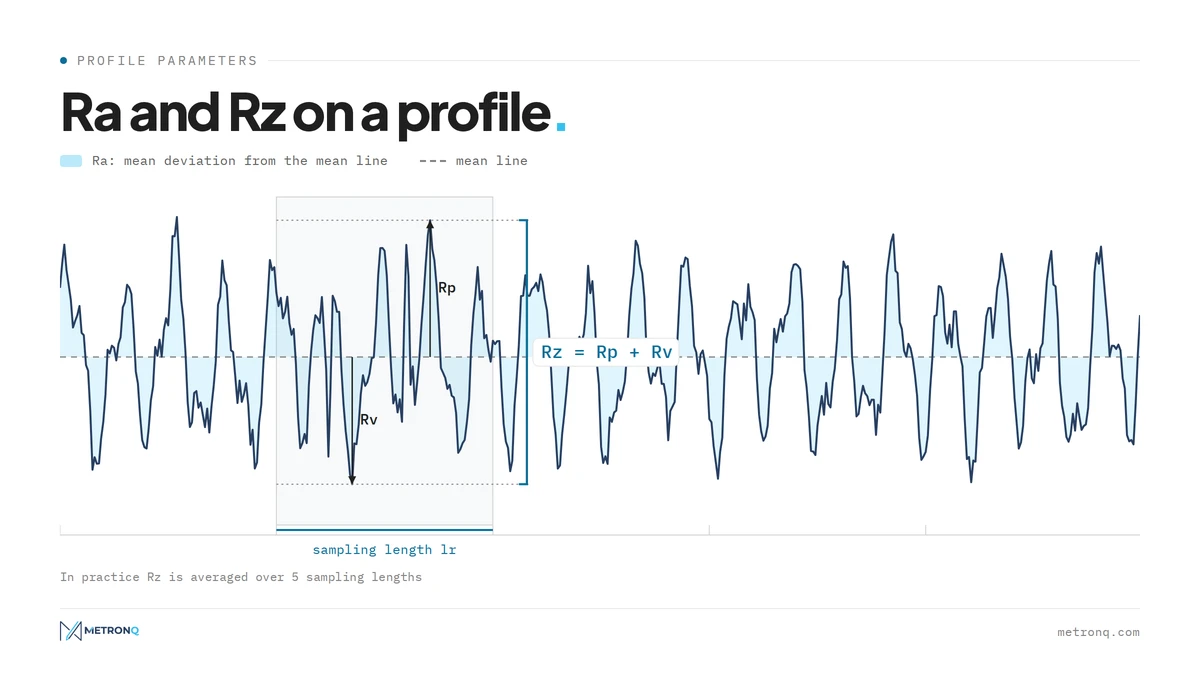
is the maximum height of the roughness profile within a sampling length: the height of the highest peak plus the depth of the lowest valley. In practice the result is averaged over five consecutive sampling lengths. The chart below shows both quantities within one sampling length.
where:
- - height of the highest profile peak above the mean line [µm],
- - depth of the lowest valley below the mean line [µm].
reacts to individual peaks and scratches, so it is used where a single asperity matters: the height of the roughness profile can disqualify a sealing face even when is fine.
Material ratio curve and other parameters
The roughness parameters do not end with those two. is the total height of the profile over the whole evaluation length, is the root mean square of the ordinates, and describes the mean width of profile elements, in other words how densely the marks are spaced. is the material ratio of the roughness profile, the share of material at a given depth. The material ratio curve (the Abbott-Firestone curve) is invaluable for sliding surfaces because it shows how much material actually carries the load after running-in. The areal parameters and to ISO 25178, calculated over an area rather than a line, appear mainly with optical measurement.
Converting Ra to Rz: an approximate table
Ra and Rz cannot be converted with a formula: the standards do not give one, because the relationship depends on the shape of the profile. For typical turned and milled surfaces it is assumed that is 4 to 7 times , which is enough for an initial assessment of a drawing or a quote.
According to George Schuetz of Mahr, a ratio of 4:1 to 7:1 is safe when an requirement is checked as , but in the opposite direction the real ratio can reach 20:1, because a single scratch drives up while hardly changing . The table shows this range for the values most often found on drawings:
| [µm] | approx. [µm] | Where you meet it |
|---|---|---|
| 0.2 | 0.8-1.4 | slideways, lapped faces |
| 0.4 | 1.6-2.8 | rolling-bearing journals |
| 0.8 | 3.2-5.6 | dynamic seals, fits |
| 1.6 | 6.4-11 | fine turning and milling |
| 3.2 | 13-22 | typical machined surfaces |
| 6.3 | 25-44 | semi-finishing |
| 12.5 | 50-88 | roughing |
Such a comparison of Ra and Rz is for an initial assessment and does not replace measurement: if the drawing specifies , is checked, and any conversion is agreed with the customer in writing.
Roughness grades: N grade table and the old 1-14 classes
A roughness grade is a conventional step of smoothness that corresponds to a limiting parameter value, usually . Two systems are still in use: the N1-N12 grades from the 1992 edition of ISO 1302, and the classes 1-14 from old Polish and Soviet standards, which assigned both and to every class.
N grades increase with roughness: N1 is the smoothest surface, N12 the roughest. The 2002 edition of ISO 1302 no longer contains them, but they still appear in catalogues, quotes and imported drawings:
| Grade | [µm] | [µin] | Example surface |
|---|---|---|---|
| N12 | 50 | 2000 | thermally cut, as-cast |
| N11 | 25 | 1000 | after roughing |
| N10 | 12.5 | 500 | free surfaces with no requirement |
| N9 | 6.3 | 250 | semi-finishing |
| N8 | 3.2 | 125 | typical machined surfaces |
| N7 | 1.6 | 63 | clearance fits, static sealing faces |
| N6 | 0.8 | 32 | fits, dynamic seals |
| N5 | 0.4 | 16 | rolling-bearing journals |
| N4 | 0.2 | 8 | slideways |
| N3 | 0.1 | 4 | lapped surfaces |
| N2 | 0.05 | 2 | measuring instruments |
| N1 | 0.025 | 1 | gauge blocks, optics |
The grades most often seen in enquiries are N7 and N8, that is 1.6 and 3.2 µm: the first needs a careful finishing pass, the second comes from correct turning or milling.
The older classes, numbered 1 to 14, run the other way: the higher the number, the smoother the surface. They come from old Polish standards and the Soviet GOST 2789, and on drawings they were written as a triangle with a number, for example ∇6. Each class has an upper limit for both parameters, which shows how that system linked to :
| Class | up to [µm] | up to [µm] |
|---|---|---|
| 1 | 80 | 320 |
| 2 | 40 | 160 |
| 3 | 20 | 80 |
| 4 | 10 | 40 |
| 5 | 5 | 20 |
| 6 | 2.5 | 10 |
| 7 | 1.25 | 6.3 |
| 8 | 0.63 | 3.2 |
| 9 | 0.32 | 1.6 |
| 10 | 0.16 | 0.8 |
| 11 | 0.08 | 0.4 |
| 12 | 0.04 | 0.2 |
| 13 | 0.02 | 0.1 |
| 14 | 0.01 | 0.05 |
In classes 1-6 is four times , in classes 7-14 roughly five times, which fits the 4-7 rule from the previous section. When roughness is given as a class, it is worth rewriting it as a specific parameter and value before quoting.
Indicating surface roughness: the roughness symbol on a technical drawing
A surface roughness indication on a drawing is the roughness symbol: two inclined legs with the parameter, its value and any additional notes next to them, for example . It tells the manufacturer which parameter to check, what value to achieve and whether the process is free to choose.
The symbol comes in three variants: basic (any process), with a bar closing the triangle (material removal required) and with a circle (material removal not permitted). Next to the symbol you can add a maximum value marked max, the surface lay, the manufacturing method and the machining allowance. On a technical drawing roughness is entered at surfaces whose requirements differ from the general requirement given collectively near the title block. We take the symbol, all its fields and the old notations apart in a separate article: surface roughness symbols on technical drawings.
How to measure surface roughness: measurement in brief
Surface roughness is measured by recording the surface profile along a line perpendicular to the machining marks and calculating parameters from it. At the machine a portable roughness tester or comparison specimens are enough, while the inspection room uses a stylus profilometer or optical methods. To compare with the drawing, the result must use the same sampling length and filter.
Stylus profilometers and roughness testers
Stylus profilometers draw a diamond stylus with a tip radius of usually 2 or 5 µm across the surface and turn its movement into a surface profile. A simple profilometer only displays numbers. A profile recorder also plots the roughness trace, from which the shape of the irregularities can be read, and an instrument with a movable stage lets you set the direction of the trace relative to the lay. A portable surface roughness tester fits in the hand and shows and within seconds, so it is used for checks at the machine.
Testing surface roughness with non-contact methods
Non-contact roughness measurement uses light: confocal microscopy, white-light interferometry or focus variation. Optical measurement does not scratch soft materials and covers an area rather than a line, so the results are given as areal parameters and . In series production roughness is usually checked on samples, and measurement normally covers only the functional surfaces. Comparison specimens give a quick indication of whether the required roughness has been reached.
We cover sampling length and filter selection, the 16% rule and reading a report in a separate guide to surface roughness measurement.
Roughness of machined surfaces: how the process shapes the result
The roughness of a machined part depends on the process, the cutting parameters and the condition of the tool. Every process produces roughness within a characteristic range, so the result can be predicted at the process planning stage: roughing removes material quickly at the expense of smoothness, and finish machining does the opposite.
The ranges below for machined surfaces come from the process selection handbook by Swift and Booker:
| Process | Achievable [µm] |
|---|---|
| Turning and boring | 0.05-25 |
| Milling | 0.2-25 |
| Drilling | 0.4-12.5 |
| Reaming | 0.4-6.3 |
| Broaching | 0.4-6.3 |
| Grinding | 0.025-6.3 |
| Honing | 0.025-1.6 |
| Lapping | 0.012-0.8 |
The ranges cover both roughing and careful finishing; the target surface reaches the lower values only in the finishing pass.
Turning
Turning leaves parallel circumferential grooves, and the surface texture is clearly directional. The theoretical height of the irregularities is set by the feed and the insert corner radius:
where:
- - theoretical profile height [mm],
- - feed per revolution [mm/rev],
- - insert corner radius [mm].
With a feed of 0.2 mm/rev and a 0.8 mm radius this gives about 6.3 µm, which means around 1.6 µm. The real result also depends on vibration, built-up edge and tool wear, so it is often worse than the theoretical one. Rough turning gives 6.3 to 25, and careful finishing with a reduced feed brings the target surface down to 0.4.
Milling
Milling leaves arc-shaped marks from the teeth and, in finish machining, gives 1.6 to 3.2. The result is governed by feed per tooth, tooth runout and strategy: climb milling usually gives a smoother surface than conventional milling, and wiper inserts allow a higher feed without losing smoothness. The lay follows the tool path, which matters when the surface texture must have a specified lay direction.
Grinding and finishing operations
Abrasive machining gives a fine, dense texture: grinding typically brings roughness down to 0.2-0.8, and fine grinding to 0.1. When the target surface needs to be smoother than that, finishing operations such as honing, lapping and polishing come in. Each such step is an additional operation, often on a separate machine.
Roughness requirements: how to specify the required surface roughness
Specifying the roughness of a part starts from its function, not its appearance. First decide which surfaces mate with other parts, then take values from bearing, seal and guide catalogues, and leave the requirements for free surfaces at the level ordinary machining delivers. This keeps costs under control and shows where roughness really matters.
Functional surfaces are usually a minority of the part. Typical milled and turned surfaces come out around 1.6-3.2 without special measures, and that level is a sensible default for free surfaces. The right roughness value for functional surfaces comes from the catalogues of mating components, because the bearing or seal manufacturer knows what its product needs. That value is then entered as the required roughness parameter with a limit.
Sealing faces and sliding surfaces
When the target surface has to seal, 1.6-3.2 is usually enough for a static seal, while a dynamic seal needs 0.2-0.8. Under a lip seal roughness is limited from below as well, because a journal that is too smooth does not hold an oil film, and the grinding marks must not form a lead that pumps oil. A slideway needs 0.2-0.8 and a rolling-bearing journal 0.4-0.8. In food and pharmaceutical installations with polishing is usually required so that nothing settles in the micro-valleys.
Surface roughness, finish and machining cost
Every step towards a smoother surface means an extra pass, a slower feed or a separate operation, and it shows in the price: what a tight tolerance and low Ra really cost. A finish of instead of 3.2 often means adding a grinding operation, and lapping on top. Roughness affects function only up to a certain threshold; below it smoothness is purely cosmetic, and finish requirements beyond that threshold raise the cost with no benefit. That is why finish parameters are best agreed with the manufacturer.
Finishing pass times are calculated for the machines the shop enters and calibrates itself, as described under machines and calibration. In automatic quoting every such step corresponds to the quality class set in the shop's quoting rules.
Frequently asked questions about surface roughness
How is the surface roughness of a part measured?
Most often with a stylus profilometer or a portable surface roughness tester: the stylus travels perpendicular to the machining marks over a standardised length, and the instrument calculates and . Optical methods are used for delicate parts. To measure surface roughness comparably with the drawing, you must use the same sampling length and filter as the requirement.
What does Ra 3.2 mean on a drawing?
It means that the average roughness, the mean deviation of the profile from the mean line, must not exceed 3.2 micrometres. It is a typical requirement for ordinary machined surfaces, corresponding to grade N8, and the standard result of correct turning. Every step down, for example to , means extra time or an extra operation for the shop.
How do you avoid errors when measuring roughness?
Measure perpendicular to the machining marks, on a clean surface and away from edges, with a sampling length and filter matched to the expected value. Typical errors are a sampling length that is too short, measuring along the grooves after turning and comparing an result with an requirement. When in doubt, the measurement is repeated at several points.
What is the roughness of machined surfaces after turning, milling and grinding?
After turning and milling 1.6 to 3.2, after careful finish turning down to 0.4, and grinding brings roughness down to 0.2 to 0.8. Honing and lapping go below 0.1, while roughing gives 6.3 to 25. In turning the feed and insert corner radius decide, in milling the feed per tooth and tooth runout.
What is the difference between roughness, waviness and form errors?
Scale and cause. Roughness is tool marks with a small spacing, usually below a millimetre, waviness has a longer spacing and usually comes from vibration, and form errors such as ovality or taper concern the whole geometry. In evaluation they are separated by filters, and on sealing faces the first two components are both controlled.
What are the roughness requirements for a sealing surface?
A static seal allows 1.6 to 3.2; for dynamic seals, for example a journal under a lip seal, 0.2 to 0.8 without lead. A single scratch can disqualify a sealing face despite a good , so it is worth specifying as well and limiting waviness. The final values are given by the seal manufacturer.
What is Rz for Ra 1.6?
Roughly 6.4 to 11 µm, because for typical turned and milled surfaces is 4 to 7 times . This is only an estimate: with individual scratches the ratio rises to as much as 20:1. If the drawing specifies , the surface has to be measured with that parameter rather than by converting an result.
Sources
- 1.EN ISO 4287 / EN ISO 21920 series (definitions of the profile parameters Ra, Rz, Rt, Rq, RSm, Rmr)
- 2.ISO 1302:1992 and ISO 1302:2002 (N1-N12 roughness grades and their removal in the 2002 edition)
- 3.GOST 2789-73 and former Polish standards: roughness classes 1-14 with limiting Ra and Rz (table e.g. in the Great Soviet Encyclopedia, entry "Шероховатость поверхности")
- 4.G. Schuetz (Mahr), "Surface Texture From Ra to Rz", Modern Machine Shop, 2002 (mmsonline.com, Rz/Ra ratio 4-7 and up to 20:1)
- 5.ISO 3274 (stylus instruments, tip radius) and ISO 25178 (areal parameters Sa, Sz)
- 6.ASME B46.1 Surface Texture (parameters in US documentation)
- 7.K.G. Swift, J.D. Booker, "Manufacturing Process Selection Handbook", Butterworth-Heinemann, 2013 (obtainable Ra ranges per process)
- 8.Sandvik Coromant, Training Handbook (theoretical profile height in turning)
- 9.R. Wołk, "Normowanie czasu pracy na obrabiarkach do obróbki skrawaniem", WNT, Warsaw 1972 (smoothness classes and their effect on the number of passes)
- 10.M. Lembersky (ed.), "Realistic Cost Estimating for Manufacturing", 3rd ed., SME, 2016 (cost of surface finishing)
Read next
Automatic CNC machining quotes
Priced from the 3D model or the drawing, on your machines and your rates. You just approve it. 14 days free, no card.
Create a free account