
Guide
Cutting Speed: Definition, Selection and Practice
· 20 min read
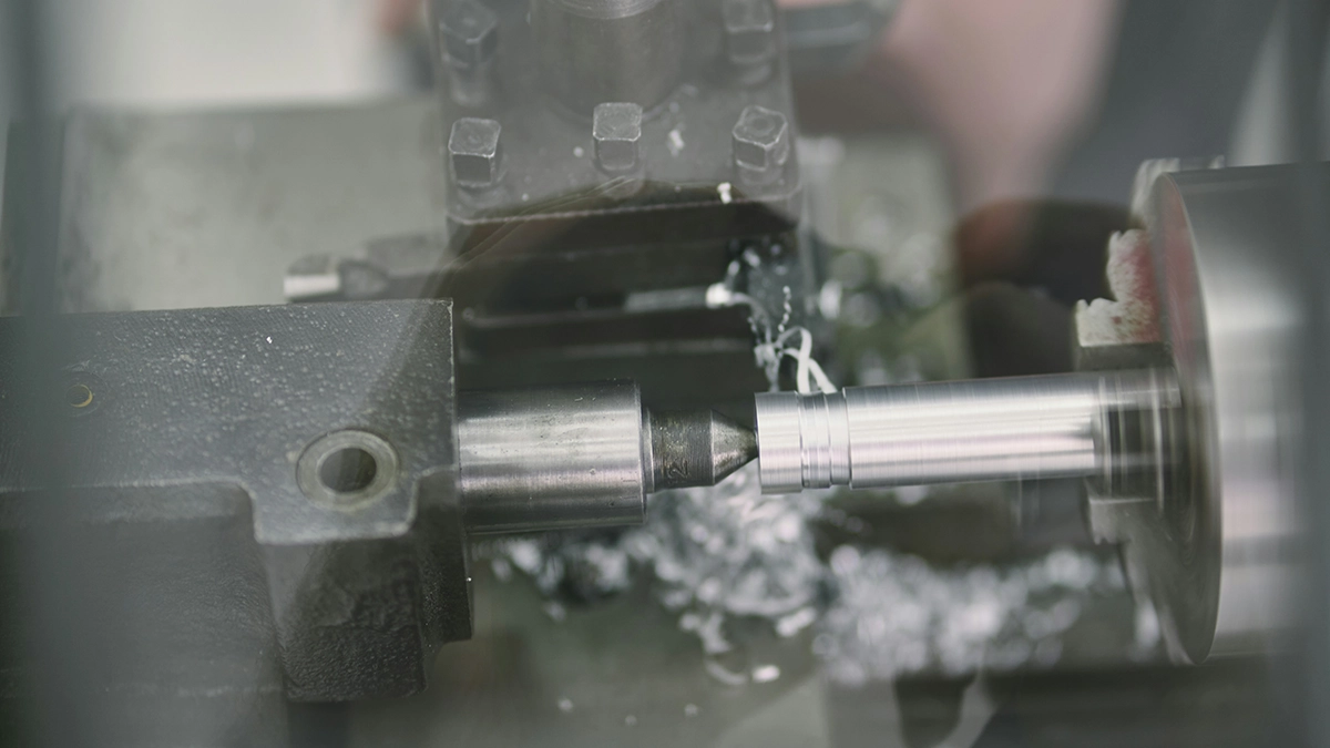
Of all the numbers that describe machining, this one does the most: cutting speed decides the temperature in the cutting zone, the rate of edge wear and whether the operation is economical at all. In this guide we explain what cutting speed is, how it differs from spindle RPM and feed, how it affects tool life and surface finish, and where to get the right value for your material.
What cutting speed is
Cutting speed (Vc) is the speed at which the cutting edge moves relative to the workpiece surface - or, put simply, how fast the edge "travels" over the material. It is expressed in metres per minute. Tool catalogues quote cutting speed in m/min rather than in revolutions, and deliberately so: RPM depends on diameter, while cutting speed describes conditions at the edge itself, whether you are turning a 20 mm shaft or a 200 mm one.
Here lies the most common misunderstanding: cutting speed is not the same as spindle speed. RPM (n, rev/min) tells you how fast the spindle rotates; cutting speed tells you how fast material flows past the cutting edge. At the same RPM, a large diameter means a high cutting speed and a small one means a low speed. That is why process planning starts with the cutting speed for the material-tool pair, and only then derives the RPM for a specific diameter. What defines it is the primary motion: in turning the workpiece rotates, in milling and drilling the tool does - so there we speak of the cutter's peripheral speed, built from the tool's rotational speed and its diameter.
Cutting speed, surface speed: one phenomenon, several names
Literature and catalogues use different names for the same quantity: cutting speed, surface speed, and in older Polish handbooks "szybkość skrawania" (the term used in Wołk's 1972 tables). They all mean exactly the same Vc. This matters when reading documentation: "cutting speed 25 m/min" in an old HSS handbook and "Vc 250" on a carbide insert card are the same physical quantity - the difference in value comes from the edge material, not the definition.
Cutting parameters: speed, feed and depth of cut
Cutting speed is the first of three parameters set before every operation. The other two are feed and depth of cut - and each of the trio is responsible for something different. Parameter selection starts with speed, because speed sets the thermal side of the process; feed and depth are added to it. The same pattern - from thermal to mechanical - will return in every section of this text.
Feed and feed rate
Feed (f) is the distance the tool travels relative to the part per revolution or per tooth - it decides how thick a chip each cutting edge takes. From feed per revolution and RPM comes the feed rate (vf, mm/min): the pace at which the tool actually moves along the part. The distinction matters: the catalogue quotes feed per revolution or per tooth, while the machine control executes a feed rate. Calculating the feed rate is simple multiplication, but it has to be done consciously - the same feed per tooth at twice the RPM gives twice the feed rate, and a higher feed rate means a proportionally shorter pass. The calculation returns at every change of RPM: the control executes mm/min, so after an RPM correction the feed in mm/min must be recalculated. A stable feed rate gives a uniform chip cross-section, which in turn means predictable cutting forces and repeatable dimensions; a feed matched to the insert also means a predictable load on the tool. Feed also directly shapes surface roughness, of which more below.
Depth of cut and width of cut
Depth of cut (ap) says how deep the edge sinks into the material in one pass; in milling there is also the width of cut (ae) - how wide a band of material the cutter takes. A typical depth of cut in rough turning is 2-5 mm, in finishing 0.2-0.5 mm. Together with feed, depth builds the cross-section of the cut layer - and therefore the mechanical load on the tool. Higher feed rates at the same depth raise productivity, but at the cost of edge load.
Cutting speed vs feed: what governs what
In short: cutting speed rules temperature, feed and depth rule forces. Excessive feed pushes the load beyond the strength of the edge (chipping); excessive cutting speed overheats it (rapid flank wear). This division of roles is the basis of diagnostics: when the edge chips, look at feed and chip cross-section; when it wears down rapidly or deforms plastically, look at cutting speed. Grzesik's textbook puts it plainly: temperature in the cutting zone grows primarily with speed, tool load with the cross-section of the cut layer. And speed influences more than heat: chip formation and the stability of the whole process depend on it too.
The character of cutting speed: what happens in the cutting zone
Machining is controlled deformation: the tool edge presses into the material, which shears along a narrow plane and flows away as a chip. Almost all the work of that shearing turns into heat, and the heating rate is set by the speed at which material flows through the shear zone. Hence the first trait: cutting speed affects temperature more strongly than any other parameter. At low speeds there is little heat, but another problem appears - chip formation becomes unstable and a built-up edge forms: hardened particles of workpiece material weld onto the edge, tear off cyclically, ruin the surface finish and micro-chip the edge. Too low a cutting speed can be just as harmful as too high. Second trait: chip character changes with speed - from torn chips, through the built-up-edge zone, to the flowing ribbon chip typical of carbide speeds; this is why cutting processes from different tooling eras look so different. Third: above a certain threshold, higher speeds stop improving anything and only shorten edge life.
What the cutting edge sees
The mechanics of the edge are described through exactly these phenomena - and they explain why there is no single "best" value: the optimum cutting speed is always a compromise between machining time and edge wear, different for every material-tool pair. Cutting speed is the superior variable in this system: every selection table starts from it, and the rest of this text shows how to find the optimum for your own process.
Cutting speed and its influence on tool life
The link between speed and tool life was quantified as early as 1907 by F.W. Taylor: his equation says that tool life falls exponentially as speed rises - so speed determines tool life more strongly than feed and depth combined. Workshop rules of thumb from the machining handbooks agree: raising cutting speed by 20% can halve tool life; raising it by 50% can cut it to a fifth. The same move in the other direction extends edge life, but at the cost of machining time. Excessive speed therefore leads to runaway flank wear, while insufficient speed leads to built-up edge, poor surface quality and wasted machine potential. Between the extremes lies a wide, safe middle: the right cutting speed is one at which insert wear is even and predictable, and changes fall into the natural rhythm of the shift.
Speed acts on the wear curve through two channels at once: temperature and friction distance. The symptoms are visible on the insert with the naked eye. Even flank wear is natural wear and the sign of well-chosen conditions. A crater on the rake face means too much temperature - usually too much speed; in extreme cases it ends in plastic deformation of the nose. Chipping and fracturing mean excessive mechanical load from feed or interrupted cuts. Built-up edge means the speed is too low. Faster-than-catalogue wear is almost never the insert's fault; it is a signal that some parameter deviates from the conditions for which the tool maker built its tables. Excessive wear is always worth diagnosing before swapping the insert for a "better" one - without that, the new insert dies the same death.
Selecting the cutting speed: where to start
Selection starts not with the machine but with two materials: the workpiece and the edge. Only then is the value corrected for the operation, the rigidity of the set-up and the required quality. Done well, parameter selection looks like a funnel: from material, through tool, to operation.
The workpiece material
The type of workpiece material is the first filter. Soft aluminium can be cut over a dozen times faster than a heat-resistant nickel alloy; hardness and work-hardening tendency decide the heat and friction at the edge. The surface of the material matters too: the hard skin of a casting or mill scale after hot rolling calls for a reduced entry speed, because the skin is often harder than the core. In austenitic steels, on the other hand, an overly timid speed leads to work-hardening of the surface layer, which the next pass then has to break through. Industry organises all this into the ISO groups: P (steels), M (stainless steels), K (cast irons), N (non-ferrous metals), S (heat-resistant alloys and titanium), H (hard materials). Group S forgives the least - titanium alloys conduct heat poorly and run at around 30-60 m/min, while group N aluminium tolerates 300-1000 m/min and more. These are materials requiring different speeds in the most literal sense: a twenty-fold difference with identical edge geometry.
The cutting tool material
The second filter is the tool material. High-speed steel (HSS) loses hardness above about 600°C, so its element is the low ranges: 25-40 m/min for structural steel. Sintered carbide works at 150-300 m/min; ceramics and CBN higher still. That is why "what cutting speed for steel?" has no answer without naming the edge - between HSS and carbide lies an order of magnitude. Older norm tables quote speeds for HSS, hence values several times lower than today's carbide ones; for the same reason, the required speed on a tool card always refers to a specific pair of material group and insert grade. Coatings play their own role: the same inserts with a PVD/CVD coating tolerate visibly higher speeds, because the coating insulates thermally and cuts friction. Which type of edge suits which job, we cover in our overview of cutting tool types.
Roughing and finishing: same material, different parameters
The third filter is the purpose of the pass. Roughing maximises material removal per unit of time: it works with a large feed and depth, and sets the speed moderately, because the chip cross-section loads the edge heavily anyway. Finishing is the reverse: small feed, small depth, higher speed - because at a small chip cross-section it is speed that gives clean shearing and good surface quality. Hence the typical pattern in the tables: for one steel grade, roughing at 180-220 m/min with a feed of 0.3-0.4 mm/rev, finishing at 240-280 m/min with 0.1-0.15 mm/rev. Well-chosen parameters always travel in pairs: speed together with feed, never separately. Badly chosen parameters are usually exactly that - "mismatched": speed from one table, feed from another; correct ones come from a single row of the catalogue. Selection for roughing and finishing is, in practice, two neighbouring rows of the same table.
Typical values: an orientation table for carbide turning
| Workpiece material | Cutting speed [m/min] | Feed [mm/rev] | Depth of cut [mm] |
|---|---|---|---|
| Structural steel | 180-280 | 0.15-0.4 | 0.5-4 |
| Stainless steel | 120-200 | 0.1-0.3 | 0.5-3 |
| Grey cast iron | 150-250 | 0.2-0.5 | 1-5 |
| Aluminium and alloys | 300-1000 | 0.1-0.4 | 0.5-5 |
| Titanium and heat-resistant alloys | 30-60 | 0.1-0.25 | 0.5-2 |
| Hardened steels (CBN) | 100-180 | 0.05-0.15 | 0.1-0.5 |
The values are indicative, after the Sandvik Coromant and Grzesik handbooks; the binding value always comes from the catalogue of a specific insert for a specific material group.
Determining cutting speed in practice: catalogue, correction, calculator
In a real shop, determining the speed takes three steps. Step one: the catalogue value from the tool card - the tool maker quotes a speed in m/min for every insert and material group, usually as a range with a starting value. Step two: correction for your own conditions. The catalogue value assumes rigid clamping, a stable allowance and continuous cutting; a slender workpiece, interrupted cuts, long overhangs or dry machining are reasons to go 10-30% lower - the chosen value has to reflect the realities of the set-up, not just the table. Unusual conditions (hard casting skins, laser-cut edges) may also demand less than the tables suggest. Step three: conversion into machine settings - speed and diameter give the RPM, feed and RPM give the feed rate. The process note should bind feed, speed and depth into one set - separated, they stop matching each other.
Cutting speed, RPM and feed calculators
This is where the tools come in: a cutting speed calculator turns Vc and diameter into RPM, an RPM calculator works the other way round, and a feed calculator converts feed per revolution into millimetres per minute; it is also handy when the number of cutter teeth changes. A good calculator does not excuse you from thinking, though: the input value still has to come from the catalogue - converting feeds and speeds is exactly the level at which calculators serve people best. How the calculation goes step by step - with formulas, worked numbers and a speed table - is shown in our cutting parameters calculator. The larger tool makers have their own selection apps, such as Sandvik's CoroPlus ToolGuide, which beyond computing the speed also recommend an insert and geometry for the operation. The calculation, however, is always the finale, not the start: material and edge first, numbers second.
Why do we stress the source rather than the formula? Because computing a cutting speed is trivially easy, while choosing the right starting value is not. To compute it you need a diameter and RPM; to choose well you need to know the material, the edge and the operation. Whoever asks how to calculate the speed for milling or turning is really asking two things at once: about unit conversion and about the base value - and only the second requires knowledge. The same milled pocket can have perfectly computed RPM from a wrong base value: the arithmetic checks out, and the inserts crumble every ten minutes. The right value comes from the catalogue and experience; the calculator only converts units, and only a right value at the input makes the output worth anything.
Turning and milling parameters: the workpiece dictates the terms
Turning parameters have one convenient property: the diameter at the point of cut is known directly, so the control can hold a constant cutting speed with G96 - RPM rises as the tool moves to a smaller diameter, and the workpiece surface sees the same conditions throughout. This stabilisation keeps the structure uniform across a whole face and the edge wear predictable. Without G96, at constant RPM, facing runs from the outside inwards with falling speed - at the axis it drops to zero, visible on the surface as a degraded finish near the centre.
In milling, the speed refers to the cutter's circumference, so the tool diameter is key - and the effective one at that: a ball-nose cutter working with its very tip has near-zero peripheral speed there, even at high RPM. That is why 3D profiling runs at RPM above what the nominal diameter would suggest. Milling's second peculiarity: the edge enters and exits the material every revolution, so the tool load pulses, and feed is counted per tooth. Low RPM with a large-diameter cutter is a normal state, not a mistake - what counts is the speed at the circumference. Finally drilling: a drill's cutting speed varies along the cutting edge (maximum at the margin, zero at the axis), which is why it tolerates lower values than a turning insert of the same carbide. What speeds your process realistically runs at is worth knowing when outsourcing, too - our instant CNC quoting computes machining time from realistic parameters, so a titanium part is priced differently from the same shape in aluminium.
Machining productivity and process economics
Productivity is measured by the volume of material removed per minute: the material removal rate is the product of speed, feed and depth. Removal grows linearly with each of the three parameters - the costs do not. The same removal rate can therefore be built in different ways, and here lies the practical wisdom of the handbooks: to remove material faster, raise depth first, feed second and speed last. Depth barely shortens insert life, feed shortens it moderately, speed exponentially. The reverse order, though intuitive ("speed it up!"), is the most expensive: more speed means shorter edge life, more frequent stoppages for changes and higher tooling cost per part.
There is a second end to this economy: undercooked parameters mean machine time flowing away for free. Norm tables list speeds separately for roughing and finishing for a reason. Wołk's 1972 tables and today's SME handbooks compute it identically: there is an economic tool life at which the sum of machine-time cost and tooling cost is smallest - and it corresponds to an economic, not maximal, speed; holding to it trims tooling cost per part without touching the cycle time. The optimum computed this way often sits 20-30% below the catalogue maximum. In practice the chosen speed usually lies somewhat below the technical maximum: high speeds buy seconds and pay in minutes of downtime; in this ledger, cutting speed is the most expensive variable to get wrong. Good parameters are recognised not by the machine "singing", but by the cost per part.
Machining quality: how feed shapes the surface finish
The full account also includes quality: higher speeds usually improve the finish (less built-up edge, cleaner shearing), but only up to the vibration threshold. When the system starts to chatter, the surface picks up characteristic vibration marks and quality falls despite the "better" parameters. The remedy is then, paradoxically, a correction downwards or a change of feed - because feed has the strongest influence on roughness height and its correction is the first move. A higher feed rate is the cheapest time gain on finishing passes, as long as the roughness spec allows it - how quality is described numerically, we cover in the article on roughness parameters.
CNC machining: what controls the speed at the machine
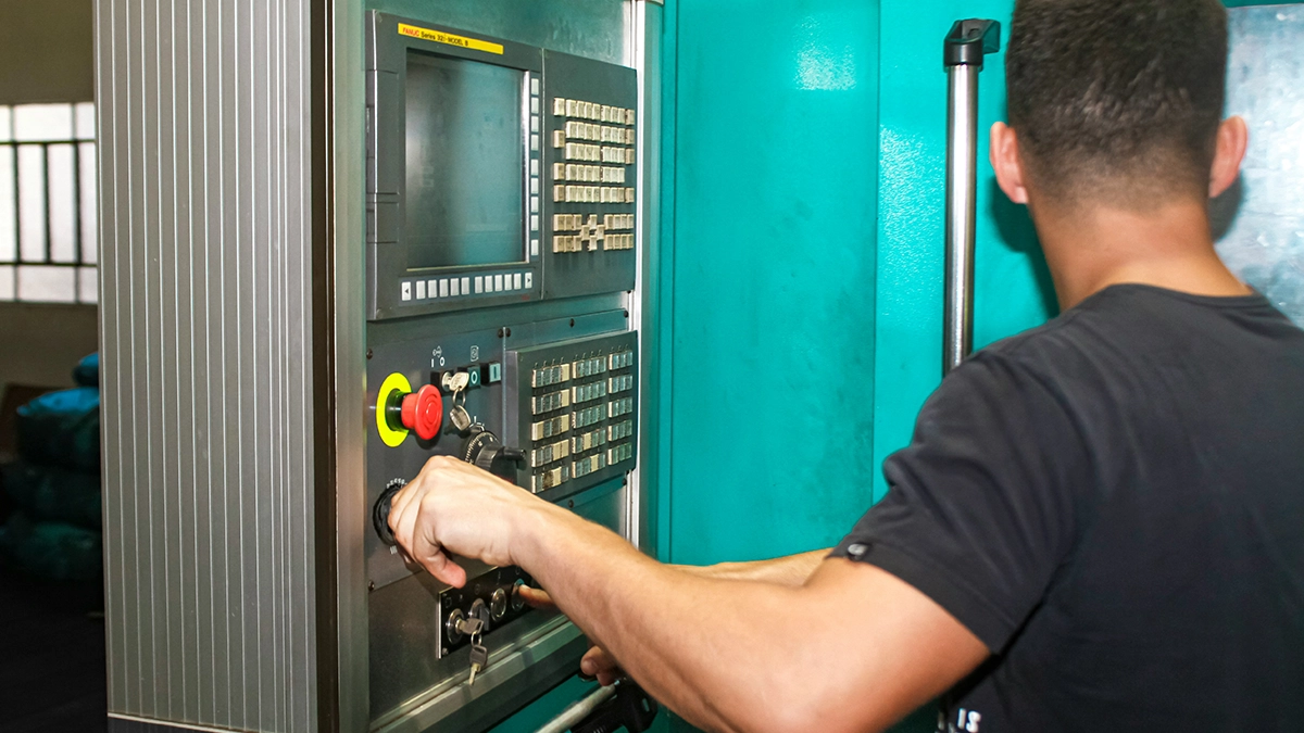
CNC machining closes the topic from the execution side: the values we chose enter the program as the S and F addresses. In turning, G96 S250 means a constant cutting speed of 250 m/min - the speed is commanded directly and the control derives the RPM from the diameter, so the chosen value holds at every diameter; G97 means constant RPM. In milling, S is always spindle RPM and F the feed rate in mm/min. Modern controls also allow on-the-fly corrections with the override dials, raising or trimming the feed as the process is dialled in - the standard way of running a process in until speed and feed prove stable. Settled values are then worth moving into the program - an override left "permanently" set is an invitation to irreproducibility. Whether the process actually holds its dimensions is verified by CNC measuring equipment: part and tool probes on the machine plus measurements on parts, because a defined speed and feed only mean something when the results repeat. A programmed feed rate delivers a repeatability no hand dial can, and holding the planned speed lets you compare insert life between batches.
Frequently asked questions about cutting speed
What is cutting speed and what is it measured in? The relative speed of the tool edge and the workpiece surface, quoted in m/min. It defines the working conditions of the edge itself, independent of diameter - which is why catalogues quote it rather than RPM.
What is the difference between cutting speed and spindle speed? Cutting speed (m/min) describes the motion of material past the edge, spindle speed (rev/min) the motion of the spindle. Diameter links them: at the same cutting speed, a smaller diameter needs higher RPM.
How do I choose parameters for roughing? Large depth and feed, moderate speed: the chip cross-section loads the edge heavily anyway. Starting values come from the insert catalogue for the material group; with unstable clamping, go 10-30% lower, then convert into RPM and feed rate.
How does a change of feed affect the surface finish? More strongly than any other parameter: roughness height grows with the square of feed per revolution, and an even feed rate keeps the tool marks evenly spaced. To improve the finish, reduce the feed or increase the nose radius first, and only then touch the speed.
Why does parameter selection depend on the workpiece material? Because hardness, thermal conductivity and work-hardening tendency decide the temperature and forces in the cutting zone. The ISO groups (P, M, K, N, S, H) organise materials precisely for parameter selection.
How do cutting parameters affect tool life? Speed exponentially (20% faster can halve tool life), feed moderately, depth least. Hence the optimisation order: depth, feed, speed - the optimum speed always lies below the technical maximum of the edge.
What turning parameters for a changing diameter? Constant cutting speed (G96) with an RPM limit: the control holds the same conditions at the edge regardless of diameter. At constant RPM (G97) the conditions change with every pass at a different diameter.
What does the tool do when the speed is too low? It builds up an edge: material welds to the edge, tears off cyclically, spoils the surface and micro-chips the tool. A typical problem of HSS-era speeds set on a carbide insert; the right carbide speed starts where the built-up edge disappears.
What is CNC measuring equipment and why does it matter here? Part and tool probes on the machine plus instruments in the measuring room. They close the selection loop: they confirm that at the set parameters, dimensions and roughness repeat from part to part.
How do I calculate cutting speed from RPM and diameter? Multiply the circumference at the point of cut by the RPM; the result comes out in m/min. Formulas with worked examples are in our calculator article - and the feed rate works analogously: feed per revolution times RPM.
Do high cutting speeds always pay off? No - above the economic optimum, every extra percent of speed costs more in inserts and downtime than it returns in time. High speeds make sense where the machine hour is very expensive and edge changes are quick.
Which parameter do you correct first: depth, feed rate or speed? It depends on the problem: short tool life - speed down; poor roughness - feed; chatter - depth and clamping. When optimising productivity the order reverses: depth first, then feed, speed last.
How does workpiece hardness change the cutting speed? Roughly: hardness and thermal conductivity work in the same direction - the harder and less conductive the material, the lower the speed. Hardened steel needs different edges (CBN) and different values than the same steel soft - the differences reach several times.
Topicscutting speedmachiningtechnology
Sources
- 1.W. Grzesik, "Podstawy skrawania materiałów konstrukcyjnych" (Fundamentals of Machining of Engineering Materials), WNT (cutting-zone mechanics, parameter influence)
- 2.R. Wołk, "Normowanie czasu pracy na obrabiarkach do obróbki skrawaniem", WNT, Warsaw 1972 (selection of cutting conditions, economic tool life)
- 3.F.W. Taylor, "On the Art of Cutting Metals", ASME, 1907 (tool-life equation)
- 4.Sandvik Coromant, "Training Handbook: Metal Cutting Technology" (speed ranges for ISO groups, selection guidelines)
- 5.M. Lembersky (ed.), "Realistic Cost Estimating for Manufacturing", 3rd ed., SME, 2016 (tooling and time cost per part).
Read next
- Finish Machining: Types, Stages and Surface QualityFinish machining turns a rough shape into a finished part: it delivers size, smoothness and looks. We explain its types and why the process splits into stages.
- Cutting Parameters Calculator: Speed, RPM and Feed ExplainedCutting speed, spindle RPM and feed - these three numbers decide tool life, surface quality and machining time. We show the formulas, worked examples and typical values you can plug straight into a cutting parameters calculator.
- Cutting Tools: Types, Design and How to Choose the Right OnesTurning tools, mills, drills and saws - cutting tools do all the real work on a machine tool. We explain tool types, design and materials, and advise how to choose the right tool for the operation.
Try it on your own part
Create an account, upload your STEP files and compare the quotes with your own. First 14 days free, no card.
Create a free account