Dimensional Tolerance: Deviations and Limits

Tolerance is the permitted difference between the largest and the smallest size a finished part may have and still be good. On a drawing it is written as an ISO symbol, e.g. Ø25 H7, or as deviations, e.g. Ø25 +0.021/0. In this article we explain limits of size and deviations, show the ISO table of values for holes and shafts, and calculate tolerances step by step, including for bearings.
Dimensional tolerance: nominal size, limits of size and deviations
Tolerance is the difference between the largest and the smallest permitted size of a part. No part can be made exactly to the drawing dimension, so the designer specifies an interval in which the actual size must lie. The narrower the interval, the more accurate and expensive the machining, because it needs slower passes and more frequent measurement.
The reference point is the nominal size , i.e. the ideal size on the drawing from which deviations are measured. The nominal size itself need not be achievable: for an h7 shaft it lies on the upper limit of the zone, and for a g6 shaft outside the zone altogether. A part is good when its size lies between the limits of size.
The upper limit of size is the maximum size and the lower limit of size is the minimum size. Both limits follow from the deviations added to the nominal size:
where:
- - nominal size [mm],
- - upper limit of size [mm],
- - lower limit of size [mm],
- - upper deviation of the shaft [mm],
- - lower deviation of the shaft [mm],
- - tolerance [mm].
Deviations can be positive, negative or zero, while is always positive. Example: a Ø40 h6 shaft has and mm, so its limits are 40.000 and 39.984 mm and the tolerance is 0.016 mm. Deviations are given in millimetres on the drawing and in micrometres in the tables.
Hole size and shaft size: capital and lower-case letters
The standard distinguishes two kinds of features. A hole is any internal size, including the width of a slot, and a shaft is any external size, including the thickness of a key. Hole deviations are written in capitals (, ) and shaft deviations in lower case (, ), just like the class symbol: H7 is a hole, h7 is a shaft.
For a hole the formulas are the same, only with capital letters. The smallest hole and the largest shaft decide whether the joint can be assembled. The smallest shaft and the largest hole set the maximum clearance.
Internal dimensions and their tolerance
Internal dimensions, i.e. hole diameters and the widths of slots and pockets, are harder to machine and measure than external ones. That is why the hole tolerance is often one grade wider than the shaft in the same joint, e.g. an H7 hole with a g6 shaft, although ground journals often get the same grade as the hole or a finer one. Hole diameters also need different instruments: bore gauges, plug gauges or a measuring machine.
Position of the tolerance zone: letters A to ZC
The tolerance zone is the interval between the upper and lower limit, drawn relative to the zero line, i.e. the nominal size. Its width is the tolerance value, and its position relative to the zero line is set by the fundamental deviation, denoted by a letter. Together they form the tolerance class, e.g. H7 or g6.
The position is described by letters A to ZC for holes and a to zc for shafts. Letters A-H and a-h place the zone on one side of the zero line, letters K-ZC and k-zc on the other, and JS and js give a symmetric zone in which both deviations are ±IT/2. A symmetric zone is useful where a size may deviate to either side, e.g. hole spacing.
h tolerance zones and the H hole
Zones h have an upper deviation of zero: shafts have an h tolerance when their largest size equals the nominal size and the whole tolerance goes into the minus. An H hole, in turn, has a lower limit of size equal to the nominal size and the tolerance goes into the plus. The fixed h for the shaft and the fixed H for the hole are the basis of the two fit systems described below.
That is why drawn bar (usually h9 or h11) and ground shafts have an h tolerance (h6-h8): the buyer knows the bar will not be larger than nominal. Classes h are also the most common for journals carrying several parts with different fits.
ISO tolerance classes and tolerance grades
An ISO tolerance class combines a letter (position of the zone) and a number (width of the zone). The number is the tolerance grade, i.e. the standard tolerance grade IT. The ISO 286 standard provides 20 grades: IT01, IT0 and IT1 to IT18. The smaller the number, the narrower the zone for the same diameter.
The letter gives the type of zone and the number its width, so a class describes every feature unambiguously, but the same class gives different values at different diameters. ISO 286 divides nominal sizes into ranges, e.g. above 18 up to 30 mm, and within each range the IT tolerance has a single value. The lower bound of a range is excluded and the upper bound included: a nominal size of exactly 30 mm belongs to the 18-30 range. Nominal sizes themselves are, by good practice, chosen from series of preferred numbers, e.g. 16, 20, 25, 32 and 40 mm.
The tolerance value follows from the tolerance factor , which grows with the cube root of the diameter: for IT7 the tolerance is , for IT11 it is . The tolerance factor explains why Ø100 h7 has a wider zone than Ø10 h7 although the grade is the same. Exact numbers always come from the tables of the standard, because they were rounded.
Grade groups: IT01-IT5, IT6-IT11 and IT12-IT18
Grades IT01, IT0 and IT1 to IT5 apply to gauge blocks, gauges and measuring instruments and to the most accurate parts, such as bearing raceways. IT0 and IT01 are practically laboratory grades. Grades IT6 to IT11 cover machine parts working in fits, and IT12 to IT18 free sizes, semi-finished products, forgings and castings. How these values are built is covered in our article on IT tolerance grades.
ISO tolerance table: hole tolerances H6-H14 and shaft tolerances h6-h14
The table below gives IT values in micrometres according to ISO 286-1 for grades 6-14. For an H hole the lower deviation is zero and the upper equals the table value. For an h shaft it is the other way round: and is minus the table value. Tolerances H6-H14 cover almost all machining.
| Diameter [mm] | IT6 | IT7 | IT8 | IT9 | IT10 | IT11 | IT12 | IT13 | IT14 |
|---|---|---|---|---|---|---|---|---|---|
| up to 3 | 6 | 10 | 14 | 25 | 40 | 60 | 100 | 140 | 250 |
| over 3 to 6 | 8 | 12 | 18 | 30 | 48 | 75 | 120 | 180 | 300 |
| over 6 to 10 | 9 | 15 | 22 | 36 | 58 | 90 | 150 | 220 | 360 |
| over 10 to 18 | 11 | 18 | 27 | 43 | 70 | 110 | 180 | 270 | 430 |
| over 18 to 30 | 13 | 21 | 33 | 52 | 84 | 130 | 210 | 330 | 520 |
| over 30 to 50 | 16 | 25 | 39 | 62 | 100 | 160 | 250 | 390 | 620 |
| over 50 to 80 | 19 | 30 | 46 | 74 | 120 | 190 | 300 | 460 | 740 |
| over 80 to 120 | 22 | 35 | 54 | 87 | 140 | 220 | 350 | 540 | 870 |
| over 120 to 180 | 25 | 40 | 63 | 100 | 160 | 250 | 400 | 630 | 1000 |
Reading example: a Ø50 H8 hole has a tolerance of 39 µm, so its lower limit is 50.000 mm and its upper limit 50.039 mm. A Ø50 h8 shaft has the same 39 µm, but in the other direction: from 49.961 to 50.000 mm. Hole tolerances H6-H14 and shaft tolerances h6-h14 have identical values and differ only in direction. For letters other than H and h, e.g. g, k or p, the deviations come from the ISO 286-2 tables.
How to choose a tolerance class
Choosing a tolerance class starts with function: does the size affect a fit, a seal or the location of another part, or is it a free size? Choosing a tighter class than the function requires only raises cost, so the rule is: the loosest possible tolerances that still guarantee function.
The most common grades in machine building are IT6 and IT7 for fits (H7 holes, g6, h6, k6 shafts), IT8-IT9 for less critical joints and IT11-IT12 for sizes that just have to fit. Finish turning usually reaches IT7-IT8, reaming IT7 and grinding IT5-IT6. The most popular grades therefore match what typical machining delivers cheaply.
Choosing the grade is also a trade-off with cost: each finer grade means a zone roughly 40% narrower and often an additional operation. So leave the loosest possible tolerances on all sizes that do not work in a fit. For every feature the tolerance class should follow from its job in the assembly.
Hole and shaft tolerances in fits
Hole and shaft tolerances are chosen in pairs, because the joint depends on the difference between their sizes. In the hole basis system the hole is always H, and the fit is written as a fraction, e.g. Ø25 H7/g6. The limits of both parts give a clearance or an interference, i.e. the type of fit.
A clearance fit always gives clearance, an interference fit always interference, and a transition fit can give either, depending on the actual sizes. With H7 holes the shaft alone decides the type of fit: g6 gives clearance, k6 a transition fit and p6 interference. Press fits are interference fits with letters p, r and s, assembled with a press or by heating. A detailed description of fit types and a table of clearances is in our fit tolerance chart.
Shaft tolerance and how to select it
The shaft tolerance depends on what runs on it: a bearing, a keyed gear, a seal or a plain bush. Selecting the shaft tolerance starts from the chosen fit and only then from machining capability. A keyed gear typically needs k6, a plain bush f7 and a radial shaft seal h11.
Fits with several parts at once mean that one shaft carries several classes on different journals. The bearing seat usually has the highest accuracy, while journals for hubs may be one grade coarser. The selection is always checked against whether the grinder or lathe in the shop can hold these fits in series production, not just on the first part. Thermal expansion also matters, because the tables apply at 20°C.
The basic hole and the hole basis system
The basic hole is an H hole whose lower limit coincides with the nominal size. In the hole basis system all holes have the deviation H, and fits are obtained by changing the shaft. Within the ISO system this is the standard in machine building, because an H7 hole is made with a fixed-size reamer and checked with a single gauge.
In the shaft basis system it is the other way round: the shaft has class h and the fit is changed by the hole letter. It is used for shafts made of drawn h9 bar, for several parts on one plain shaft and for bearing housings. The choice of fit system belongs to the designer: with the hole basis the shop needs fewer tools and gauges, while with the shaft basis it needs a reamer for every hole letter. That is why the hole basis is chosen almost every time, and the H7 hole diameter is the most common class in the shop.
The size of an interference joint is calculated just like clearance, only the result is negative. For Ø25 H7/p6 the minimum interference is 1 µm and the maximum 35 µm. This value decides the press-in force and whether the joint transmits torque without a key. A chosen interference fit is always checked for both extreme cases.
General tolerances ISO 2768 and dimensions without a symbol
General tolerances apply to sizes for which the drawing gives no deviations. ISO 2768-1 sets them in four general tolerance classes: f (fine), m (medium), c (coarse) and v (very coarse). The chosen class is entered once in the title block, e.g. ISO 2768-m, and from then on it applies to all toleranced sizes without their own indication.
| Length [mm] | f | m | c | v |
|---|---|---|---|---|
| 0.5 to 3 | ±0.05 | ±0.1 | ±0.2 | - |
| over 3 to 6 | ±0.05 | ±0.1 | ±0.3 | ±0.5 |
| over 6 to 30 | ±0.1 | ±0.2 | ±0.5 | ±1 |
| over 30 to 120 | ±0.15 | ±0.3 | ±0.8 | ±1.5 |
| over 120 to 400 | ±0.2 | ±0.5 | ±1.2 | ±2.5 |
| over 400 to 1000 | ±0.3 | ±0.8 | ±2 | ±4 |
| over 1000 to 2000 | ±0.5 | ±1.2 | ±3 | ±6 |
| over 2000 to 4000 | - | ±2 | ±4 | ±8 |
General tolerance classes are symmetric, so the size may deviate to either side. A length of 50 mm in class m is toleranced ±0.3 mm. Class m is the most common in machining, class c in welding and sheet metal work. They apply to linear sizes, radii, chamfers and angles, but not to sizes with their own deviation or to auxiliary dimensions in brackets.
General tolerances are simply the loosest tolerances the designer accepts, so there is no cheaper machining than that. In many shops they are informally called workshop tolerances.
Geometrical tolerances according to ISO 1101
Geometrical tolerances limit the form, orientation, location and run-out of surfaces, i.e. what size alone does not describe. A shaft can be within h6 along its whole length and still be tapered or bent. Geometrical tolerances are written in a feature control frame according to ISO 1101, with a symbol, a value and datums.
Geometrical tolerances fall into four groups. Form tolerances are straightness, flatness, roundness and cylindricity. Orientation tolerances are parallelism, perpendicularity and angularity. Location tolerances are position, coaxiality and symmetry, and run-out tolerances are radial, axial and total run-out. For cylindrical features, cylindricity and radial run-out are the most common callouts on bearing journals.
Under the independence principle of ISO 8015, size and geometrical tolerances apply separately. Anyone who wants the shaft diameter to limit its form as well adds the envelope requirement, the circled E symbol. Geometrical tolerances larger than the size tolerance are permitted and often used on non-functional surfaces. If the drawing has no frames, the general geometrical tolerances of ISO 2768-2 apply in classes H, K or L.
Larger geometrical tolerances usually mean cheaper machining, because of fewer setups and measurements. Larger tolerances are also worth leaving where the part is adjusted during assembly anyway. Tolerances should always follow from function, not habit, and they should be verifiable with the instruments the shop has.
Dimensional tolerance calculator: how to calculate a tolerance step by step
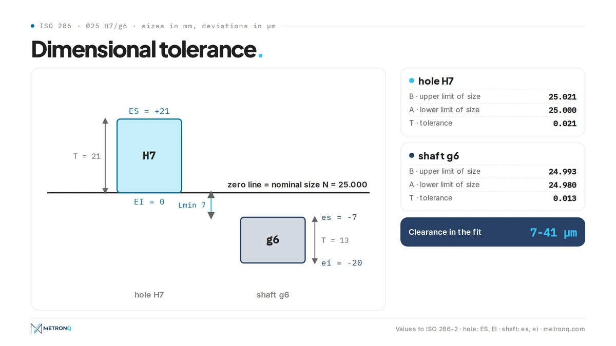
A dimensional tolerance calculator converts an ISO symbol into deviations and limits without searching the tables. You enter the diameter, choose hole or shaft, the letter and the grade, and get both deviations, the value and both limits of size. By hand it takes four steps, shown below for a Ø25 H7 hole and a Ø25 g6 shaft.
- Find the range the diameter falls in, e.g. Ø25 mm belongs to the range over 18 to 30 mm.
- Read the IT tolerance for the grade from the tables, e.g. IT7 = 21 µm.
- Read the fundamental deviation of the letter: for H the lower one is 0, so the upper is +21 µm and the hole tolerance is 21 µm.
- Add the deviations to the nominal size: lower limit 25.000 mm, upper limit 25.021 mm.
The same calculator gives the Ø25 g6 shaft: from 24.980 to 24.993 mm. The smallest hole (25.000) minus the largest shaft (24.993) gives a minimum clearance of 7 µm, and the largest hole minus the smallest shaft a maximum clearance of 41 µm. Our free tolerance calculator does this for any pair, with values according to ISO 286 and ISO 2768.
The calculator uses the tables of the standard, not the tolerance factor formula, because the formula differs by 1-2 µm from the rounded standard values. Different deviations for the same class come from the ranges: Ø18 h7 and Ø18.5 h7 fall into different ranges, so their deviations differ. A good calculator also shows the hole and shaft tolerances side by side, together with the clearance or interference.
Bearing tolerance calculator: shaft and housing for a bearing
A bearing tolerance calculator has to account for the bearing's own tolerances according to ISO 492. The bore of the inner ring in the normal tolerance class has a zone only in the minus: for diameters over 18 to 30 mm from 0 to -10 µm. The outer ring also has a minus tolerance, for diameters over 50 to 80 mm from 0 to -13 µm.
Example: a 6205 bearing (25 mm bore) on a Ø25 k5 shaft. The shaft measures 25.002 to 25.011 mm and the bearing bore 24.990 to 25.000 mm. The interference is therefore 2 to 21 µm, although the H7/k6 pair is a transition fit in the fit table. That is why the class for a bearing seat is chosen from the bearing manufacturer's catalogue, most often k5, k6 or m5 for the shaft and H7 or J7 for the housing.
Tolerance dimensioning and ISO tolerance designations on the drawing
Tolerance dimensioning means adding information about permitted deviations to the nominal size. The drawing standards ISO 14405-1 and ISO 129-1 allow three methods: a class symbol (Ø25 H7), numerical deviations (Ø25 +0.021/0) or both limits (25.021/25.000). Each means the same, but the ISO symbol is the shortest and immediately tells you which gauge checks the diameter.
ISO tolerance designations are a system used throughout Europe and most of the world, so any shop can read a drawing with H7. The ISO tolerance system is described by the two parts of ISO 286: part 1 (principles and IT values) and part 2 (tables of deviations). The ISO class symbol alone is sufficient, but deviations are often added in brackets next to it, e.g. Ø25 H7 (+0.021/0), so the operator does not need the tables. The bracketed deviations are then for information only, and if they differ from the tables they must be corrected.
Tolerance indications also apply to angles and lengths. Tolerance designations must be unambiguous: the second element of a tolerance specification, next to the value, is the information on which surface it refers to. A feature tolerance applies to one surface, not to the distance between two, so the spacing of two hole axes is better described by a position tolerance than by two deviations.
Changing a tolerance on the drawing is the designer's decision. Relaxing a feature, e.g. from H7 to H8 on a hole that does not work in a fit, can remove reaming from the process. Changing a shaft from h6 to h9 replaces grinding with turning. Every change of a feature tolerance, however, needs the approval of the author of the documentation.
Measurement: measuring instruments and actual size
The actual size is the size measured on the finished part. The part is good when it lies between the limits of size. Measuring instruments are matched to the tolerance value: a common metrology rule says the instrument resolution should be about 1/10 of the tolerance, and measurement uncertainty should not consume more than about fifteen percent of the zone.

A calliper with 0.02 mm resolution is enough for class m of ISO 2768, a micrometer with 0.01 mm or 0.001 mm resolution for grades IT7-IT8. In series production holes and shafts are checked with gauges: plug gauges for holes and snap or ring gauges for shafts. For small and deep holes a plug gauge is often the only practical instrument. The go side of the gauge corresponds to the limit the part must pass, and the no-go side to the other limit.
Dimensional tolerances and machining cost
Dimensional tolerances are among the strongest drivers of part price. Going from IT11 to IT7 on the same diameter usually adds a finishing operation, more frequent measurement and more scrap, and going to IT6 often requires grinding. That is why dimensional tolerances are specified only where the function of the part demands them.
How tolerances translate into time and price is covered in tolerances vs CNC machining cost. In MetronQ quoting, tolerances and roughness act as time multipliers set by the shop, and the shop panel shows how much time and cost each operation on the part adds.
Frequently asked questions about dimensional tolerances
How do I calculate dimensional tolerances?
Tolerance is the difference between the limits or the deviations: upper deviation minus lower deviation. For Ø25 H7 the deviations are +0.021 and 0 mm, so the tolerance is 0.021 mm and the diameter must lie between 25.000 and 25.021 mm. For ISO symbols the deviations come from the ISO 286-2 tables or a calculator.
How do I choose a tolerance class for a dimension?
The tolerance class is matched to the function of the size and the machining method. Diameters in fits usually get IT6-IT7, less critical joints IT8-IT9, and free sizes a class from ISO 2768. It always pays to choose the loosest class that guarantees function, because each finer grade raises machining cost.
What is a workshop tolerance?
Workshop tolerance is an informal term for the tolerance that applies when the drawing gives no deviations. Today it is defined by ISO 2768 through a class entered in the title block, e.g. ISO 2768-m. If the drawing has no such entry, the shop should agree with the customer which tolerance to apply instead of guessing and risking a complaint.
Which measuring instruments are used to check tolerances?
Measuring instruments are chosen so that their resolution is about 1/10 of the tolerance. For free sizes a calliper is enough, for grades IT7-IT8 a micrometer or bore gauge, and in series production plug and snap gauges. The narrowest zones and form tolerances are measured on a coordinate measuring machine at controlled temperature.
Can a tolerance on the drawing be changed?
Only the author of the documentation, or someone they authorise, can change a tolerance. The shop can propose relaxing it when the size does not work in a fit, because that often removes a whole operation from the price. Every change should go into the drawing as a new revision so that quality control checks the part against current requirements.
Sources
- 1.ISO 286-1:2010, Geometrical product specifications (GPS) - ISO code system for tolerances on linear sizes - Part 1: Basis of tolerances, deviations and fits
- 2.ISO 286-2:2010, Part 2: Tables of standard tolerance classes and limit deviations for holes and shafts
- 3.ISO 2768-1:1989, General tolerances - Part 1: Tolerances for linear and angular dimensions without individual tolerance indications
- 4.ISO 2768-2:1989, General tolerances - Part 2: Geometrical tolerances for features without individual tolerance indications
- 5.ISO 1101:2017, Geometrical tolerancing - Tolerances of form, orientation, location and run-out
- 6.ISO 8015:2011, Fundamentals - Concepts, principles and rules (independence principle)
- 7.ISO 14405-1:2016, Dimensional tolerancing - Part 1: Linear sizes
- 8.ISO 492:2014, Rolling bearings - Radial bearings - Geometrical product specifications (GPS) and tolerance values
- 9.ANSI B4.2-1978 (R2020), Preferred Metric Limits and Fits
- 10.SKF, "Rolling bearings" - general catalogue (bearing tolerances, shaft and housing fits)
- 11.Z. Osiński (ed.), "Podstawy konstrukcji maszyn", PWN (selection of tolerances and fits)
Read next
Automatic CNC machining quotes
Priced from the 3D model or the drawing, on your machines and your rates. You just approve it. 14 days free, no card.
Create a free account