Surface Roughness Symbols and Callouts on Technical Drawings
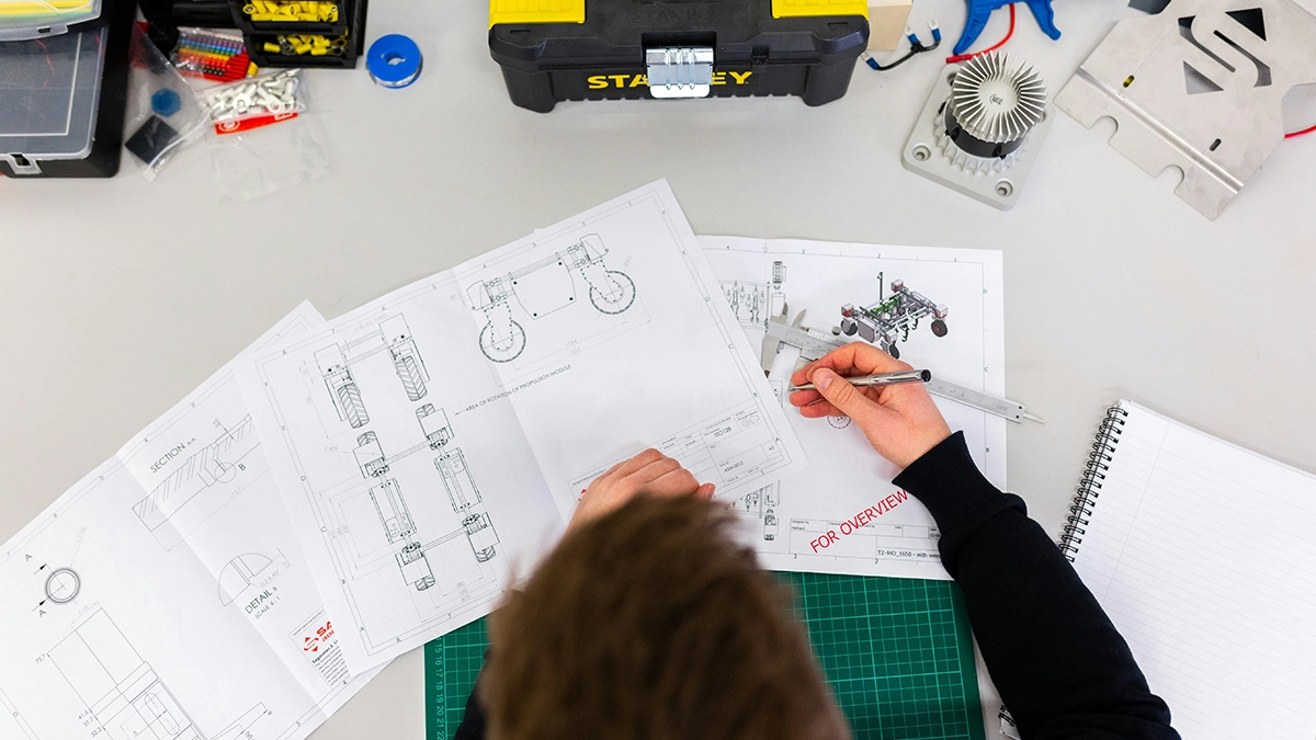
Roughness symbols are standardised drawing callouts that tell the manufacturer how smooth each surface must be: the roughness symbol, the parameter value, the manufacturing method and the lay direction. Today the rules are set by ISO 21920-1, previously by ISO 1302. In this guide we show how roughness is indicated under current standards, how to read the symbols on other people's drawings and on old ones, and how to write your own requirements so that the manufacturer understands them exactly as you do.
Surface roughness: a short refresher
Surface roughness is the finest component of a part's geometry: the micro-irregularities left by the cutting edge, the grinding wheel or another process, which surface profile analysis separates from waviness and form errors. In mechanical engineering and metalworking it is one of the basic requirements on any drawing.
It ends up on the drawing because it affects friction, sealing, fatigue and appearance - and every step down in smoothness means extra operations and a higher cost.
The broader topic - how differs from , how roughness is measured and what finish turning or grinding really achieves - is covered in the article on surface roughness parameters. Here we deal with what you see on the drawing: the symbol and everything that stands next to it.
ISO 1302 or ISO 21920: which ISO standard to read the symbol by
A symbol is read by the standard cited in the title block; if the drawing invokes ISO 1302, its default rules apply, and when migrating to the new standard the callouts deserve a review, as the defaults differ. If the title block is silent, assume the ISO 21920 interpretation and confirm it with the designer at the first article.
The new standard, ISO 21920-1:2021, replaced ISO 1302:2002, but most drawings in circulation were still made "the old way". The shape of the symbol, the place of the value at the shelf, the lay symbols and the meaning of the callout have not changed. The new series brought together what used to be spread across ISO 1302 (indication), ISO 4287 (roughness parameters) and ISO 4288 (acceptance rules), and made the defaults explicit, for example the acceptance rule and the evaluation length.
The roughness symbol: anatomy
The basic roughness symbol is a "check mark" of two arms at 60° to the surface line, placed on an edge of the view or on a leader line. Around it the standard arranges everything else: the required parameter and its value (e.g. 3.2) under the horizontal shelf, and additional symbols for the process and lay near the vertex.
The symbol always points at a specific target surface: it touches it directly or connects to it with an arrow, so it is clear where the roughness value required by the designer applies. The complete symbol has five fixed fields, labelled with letters in the standard, which is why symbols from different design offices read the same way:
| Field | Position at the symbol | What goes there | Example |
|---|---|---|---|
| a | under the shelf, first line | required parameter and value | |
| b | under the shelf, further lines | second and further requirements | |
| c | above the shelf | manufacturing method, machining, coating | ground |
| d | at the vertex | lay symbol | |
| e | on the left, at the arm | machining allowance in mm | 0.3 |
Three variants of the roughness symbol
The symbol comes in three variants that tell the manufacturer whether the process is their choice. The basic symbol (the bare check mark) means the surface may be produced by any method. The symbol with a closed triangle requires material removal: the target surface must be machined or ground, as on classic machined surfaces. The symbol with a circle inscribed between the arms prohibits material removal: the surface must stay as it came from casting, forging or rolling.
This third variant is the one most often ignored - and the one that takes the most expensive revenge. On forgings and castings the raw surface layer is more valuable than a machined one: it carries favourable residual stresses and a closed structure, and removing it can lower the fatigue strength of the part. A manufacturer who "improves" such a surface makes a part that does not conform to the drawing, even if it comes out smoother.
A fourth variant is the "all around" symbol: a small circle where the arm meets the shelf. It means the requirement applies to all surfaces on the closed outline in the given view, but not to faces parallel to the drawing plane. It must not be confused with the circle between the arms, which prohibits machining.
Ra and Rz roughness: how to read the number at the symbol
The core of the callout is the parameter value, a limit. is the average roughness, the arithmetic mean of profile deviations from the mean line, and the height of the roughness profile from peak to valley; both are always in micrometres. They are written as parameter symbol, space, value, e.g. or .
That is enough to read the required value at the symbol: 3.2 on a journal means the average roughness of that surface must not exceed 3.2 µm. Which parameter to choose and why is the stricter sieve for single scratches in the profile is the domain of the parameters article. For the callout one thing matters: a single symbol can carry values for several parameters at once, and each of them applies separately.
Ra, Rz and other roughness parameters at the symbol
Any roughness parameter from the standard can be written at the symbol, not just and : for example the total height of the roughness profile or the material ratio . The leading letter says which profile the parameter is calculated from: R is the roughness profile, W the waviness profile and P the primary profile. There is one condition: the parameter symbol always comes before the number.
Maximum roughness callouts and other entries at the symbol
By default a single value works under the 16% rule: a batch conforms if no more than 16% of measurement results exceed the limit, with the values from each measurement compared against it. When the requirement is critical, a "max" callout is used, e.g. : the limit must then not be exceeded in any single measurement.
The max form is standard on sealing and bearing surfaces, where maximum roughness decides tightness and one scratch means a leak. It also appears in hygienic installations: surfaces in contact with food usually have no greater than 0.8 µm. Besides the parameter value, the symbol can carry the machining method, the allowance, the evaluation length and a value of a second parameter type, so a complete instruction fits into one symbol: "ground, 0.8, lay perpendicular to the axis".
Some surfaces must be neither too rough nor too smooth: lapped contact faces, surfaces for adhesive bonding, cylinder bores. For them a two-sided callout with the letters U and L is used: means the roughness has to fit inside a band - too rough will not seal, too smooth will not hold lubricant or adhesive. Deleting the lower limit "for simplicity" when redrawing documentation is an easy way to get an assembly that seizes.
Surface treatment callouts: surface finish, coatings and heat treatment
Surface treatment is written in words above the shelf, in field c: "turned", "ground", "lapped", "polished". Such a note imposes the process on that target surface, so it is used only when the surface finish matters functionally; the value alone says only what roughness the finished face must have and leaves the method to the shop.
The same field is used for coatings. If the required roughness value applies to the state before coating, this must be stated explicitly, because the coating changes the profile. Finish requirements can therefore carry two values: one for the substrate before coating and one for the finished surface.
Heat treatment is specified on a technical drawing separately, outside the roughness symbol. The rules are given in ISO 15787: hardness with a tolerance (e.g. 58+4 HRC), the depth of the hardened layer and the extent of treatment. A locally hardened zone is marked with a thick chain line along the surface.
Lay direction on machined surfaces
The lay, i.e. the direction of the machining marks, is indicated with a letter or symbol at the vertex of the roughness symbol. Every machined surface has some lay, and a profile measured along or across the marks looks completely different; the roughness profile height is greatest across the lay, so profilometry and roughness inspection measure across it.
The standard provides seven lay symbols: marks parallel to the projection plane of the view, perpendicular to it, crossed, multidirectional (typical of face milling), concentric, radial and non-directional, particulate (e.g. after abrasive blasting). The lay also affects how an assembly works: a sliding surface runs quieter when the marks follow the motion, and a radial seal needs circumferential marks. Wherever the target surface works against a seal or a guideway, write the lay explicitly: the value alone does not say how the surface will behave in motion.
Roughness grades and roughness tables
Before roughness callouts were standardised as direct parameter values, smoothness was written as grades. Roughness grades are conventional steps, or levels of surface roughness, each corresponding to an average roughness value; the lower the N grade number, the smaller the roughness height (the old ∇ classes run the other way). The units stay the same: micrometres.
The modern ISO grades are N1-N12; older Polish and Eastern European documentation uses the triangle classes ∇1-∇14 from former national standards. Roughness tables let you move quickly between the notations:
| ISO grade | [µm] | Legacy mark | Typical process |
|---|---|---|---|
| N12 | 50 | ∇1 | flame cutting, raw casting |
| N11 | 25 | ∇2 | rough machining |
| N10 | 12.5 | ∇3 | rough turning, milling |
| N9 | 6.3 | ∇4-∇5 | medium machining |
| N8 | 3.2 | ∇6 | typical machined surfaces |
| N7 | 1.6 | ∇7 | fine turning and milling |
| N6 | 0.8 | ∇8 | precise machining, grinding |
| N5 | 0.4 | ∇9 | fine grinding |
| N4 | 0.2 | ∇10 | grinding, honing |
| N3 and below | ≤0.1 | ∇11-∇14 | lapping, polishing |
Grade-style general descriptions are still used in commercial specifications; this is how the metal industry describes roughness, for example when assessing the surface quality of steel bars in the as-rolled state. Roughness described this way is a property of the semi-finished product, not of the finished part; in mechanical engineering it is specified directly as an value.
Old roughness symbols: how to read legacy drawings
Old callouts are read by the standard in force when the drawing was made, not by today's. ISO 1302:2002, the former roughness indication standard, states it plainly: a callout to an earlier edition refers to the parameter definitions of its time and can only be read that way. Check the date and standard in the title block first.
In practice the shop meets four kinds of legacy roughness callouts:
- Triangles with a class number (∇6, ∇8). Roughness classes from former Polish and Eastern European standards; the equivalents are in the table above.
- Bare triangles without a number (∇, ∇∇, ∇∇∇). Typical of old German documentation (DIN 3141, replaced by DIN ISO 1302 around 1980): the more triangles, the smoother the surface, while a tilde ~ marked a raw surface. The numerical value has to be agreed with the designer.
- A bare number to the left of the symbol, e.g. 3.2. Under ISO 1302 before 2002, a number without a parameter symbol meant in micrometres. On new drawings such a callout is incomplete.
- on a drawing from before 1997. Previously meant the ten-point height of the roughness profile; today it is the maximum height of the roughness profile (formerly ). Same letter, different quantity, because the roughness parameters were redefined at that time.
The changes to roughness indication introduced in 2002 were the fixed fields a-e, the mandatory parameter symbol, the 16% rule as the default and the "max" suffix. For spare parts for old machines, the safest approach is to rewrite the requirement in today's notation and confirm it with the customer.
The collective indication at the title block
A complete drawing does not put a symbol on every face; that is what the collective indication above the title block is for, serving as the general roughness description of the whole part. It works like a default: a symbol with a value (most often 3.2 for machined surfaces) applies to every surface without its own symbol.
That is the roughness the rest of the part must have, on external faces and inside bores alike, so one callout covers every face; 3.2 is the typical value in metalworking. If the part has functional surfaces with individual requirements, the symbol or symbols of the exceptions are added in brackets next to the collective symbol - a signal to the reader: "the rest is 3.2, but look through the views for surfaces marked otherwise". Two things break this system most often: a collective symbol without the brackets on a part with individual callouts, and no collective indication at all, when surfaces without a symbol carry no requirement.
How to indicate roughness on a technical drawing: step by step
Roughness indication is simplest in six steps: pick the functional surfaces, choose the parameter and value, decide on the acceptance rule, add the process and lay only where they matter, place the symbols on the right edges and close the drawing with a collective indication.
- List the functional surfaces. Contact faces, journals for bearings and seals, sliding and datum surfaces. Only these need their roughness specified with a separate symbol.
- Choose the parameter and value. Usually ; the value follows from the function of the surface, not from a safety margin.
- Decide on the acceptance rule. The default 16% rule is usually enough; use max only for critical surfaces.
- Add finish requirements if needed. The process in field c and the lay symbol at the vertex; otherwise leave them empty.
- Place the symbol on the edge or a leader line. From the side where the target surface is visible; one symbol describes one surface.
- Add the collective indication above the title block. With the exceptions in brackets, so that the roughness of every face of the part is defined.
This makes the roughness indication complete: every face has its requirement, explicit or default, and functional surfaces get theirs directly. External roughness, on visible and datum surfaces, is easy to achieve and inspect. Internal roughness, in bores and grooves, can be harder: it gets its symbol on a leader line with an arrow pointing into the bore, and below 0.8 in a deep bore usually means an extra operation, such as reaming. Internal roughness therefore costs more than the same value on an external surface.
If only a fragment of a feature needs a different finish from the rest (say, just the bearing seat section of a journal), the symbol is placed at that fragment with limit lines marking its extent; that is the simplest way to specify roughness only where it is needed. We have gathered the whole topic of roughness on drawings onto a single A4 page: a PDF cheat sheet of roughness symbols to print and pin up by the workstation.
Five drawing callouts and what the process engineer reads in them
One housing drawing can carry five typical callouts: a collective symbol, a triangle with 0.8 on a contact face, grinding with on a journal, a U/L band on a bonded surface and a circle symbol on a forging. Each tells the process engineer something different about the process, the cost and the roughness of the part.
This information then goes into the process sheet:
- A collective above the title block, two exception symbols in brackets. A standard milled part; two surfaces need attention, the rest will come out "by itself" from proper machining, and roughness comparison specimens are enough to check it.
- with a closed triangle on a valve contact face. Fine machining with slow feeds, or grinding; plus roughness inspection with a profilometer on every piece, because the requirement sits at the edge of what milling can do.
- on a journal for a radial shaft seal. The process is imposed, maximum roughness is 0.4 in every measurement, marks perpendicular to the axis of rotation - so longitudinal grinding is out and plunge grinding stays. One of the most expensive combinations in the price list.
- on a bonded surface. A two-sided band: too smooth - the adhesive will not bond, too rough - the joint will be discontinuous. The engineer plans the machining "into the middle of the band", not as smooth as possible.
- The circle symbol on a forging surface. Do not touch: here the raw surface roughness is the requirement. If machined surfaces lie right next to it, the setups have to be planned so that no allowance is accidentally taken where there is none.
Quality requirements from a drawing can be priced automatically today: instant CNC quoting from a STEP file calculates the quality class surcharge separately for every surface. You can also upload just the technical drawing as a PDF - the documentation explains which files the quoting tool accepts.
Roughness vs cost: what is feasible
The relationship between roughness and cost is simple, because roughness drives the number of operations: proper machining, milling and turning, gives 1.6-3.2 without special measures, careful finishing 0.8, and anything below usually requires grinding or finish machining - a separate operation, often on a separate machine.
Every reduction of the permissible roughness height below 0.8 is a deliberate cost decision: the lower the required value, the more operations. Before you put 0.4 on a surface that comes off a milling cutter, it is worth knowing what that costs: how tolerances and surface finish drive the price of a CNC part. Inspection adds to the cost as well. Profilometry methods are either contact, with the profilometer traced across the lay, or non-contact, optical, and the calculated parameters are compared with the drawing; at the machine the operator reaches for roughness comparison specimens, while a metallographic microscope is used to assess the surface layer, not the roughness itself. Profilometry methods and their pitfalls are covered in the article on roughness measurement.
Common mistakes in roughness callouts
A few mistakes in roughness indication repeat on drawings often. A bare number at the symbol, leaving the parameter to be guessed: "0.8" could mean , or anything; on old drawings to pre-2002 ISO 1302 it meant , but on a new drawing it is incomplete, and the manufacturer picks the reading that suits them.
A symbol placed on the wrong side of the line, from the material side instead of the free side - formally it then specifies the roughness of a surface the designer did not mean. 0.8 on a cast surface without a machining symbol - a raw sand casting has in the order of 12.5-25, so such a requirement without the triangle demanding machining is infeasible and usually comes back as an RFQ query. A symbol on a dimension line instead of on the surface edge - the reader cannot tell which face it applies to. Finally, individual callouts without the exceptions in brackets at the collective symbol: two requirements then apply at once, and the dispute ends only at acceptance. Careful roughness indication closes each of these loopholes, because in mechanical engineering roughness is a functional requirement, not decoration.
Frequently asked questions about roughness symbols
What does a roughness symbol without any value mean?
It only states the method: the basic symbol allows any process, the triangle requires material removal and the circle prohibits it. A numerical requirement comes only with a parameter value; a bare symbol near the title block may also belong to a collective indication with exceptions in brackets. A complete callout needs a parameter symbol and a limit value.
What is the difference between Ra 3.2 and Ramax 3.2?
3.2 works under the 16% rule and allows individual results to exceed the limit (at most 16% of measurements), while with 3.2 the maximum roughness must not be exceeded in any measurement. The max form is used for critical surfaces such as sealing and bearing faces, and roughness inspection then becomes more expensive.
Is a drawing marked to ISO 1302 still valid?
Yes, the standard cited in the title block governs that drawing, even after being replaced by a newer series. The symbol shape, value position, lay symbols and meaning of the callout are unchanged in ISO 21920. The differences concern mainly the defaults, so when migrating documentation the callouts are worth reviewing rather than swapping the standard number mechanically.
How do I read old roughness symbols with triangles?
A triangle with a number (e.g. ∇6) is a former roughness class corresponding to a specific average roughness : ∇6 is about 3.2 µm, ∇8 about 0.8 µm. Bare triangles without a number usually come from old German documentation and indicate a degree of finish, so their numerical value has to be confirmed with the designer.
How do I specify roughness for only part of a feature?
With a symbol at that fragment of the surface, with limit lines marking its extent, e.g. only at the bearing seat section of a journal. That is cheaper than tightening the requirement for the whole surface and the simplest way to specify roughness only where it is needed; the rest keeps its own or the collective requirement.
How do I indicate roughness on machined surfaces?
Most often with a collective 3.2 above the title block and separate triangle symbols only on functional surfaces, e.g. 0.8 on a bearing journal. External roughness of a shaft and internal roughness of a bore get their symbol on the edge or a leader line; the lay and process are added only when they affect function.
When should surface finish be added to a roughness symbol?
Only when the machining method affects function, e.g. when a seal journal must be plunge ground or a surface must be polished. The finish is written in words above the shelf. In all other cases the parameter value is enough, and the choice of method stays with the shop, which usually lowers the price of the part.
How should roughness be measured so the result is comparable with the drawing?
The profilometer is traced across the lay, where the roughness height is greatest, over the evaluation length stated at the symbol or the default of the drawing's standard. The calculated parameters are compared with the limit under the 16% rule or max. Comparison specimens allow quick checks at the machine, but disputes are settled by the instrument.
Downloads
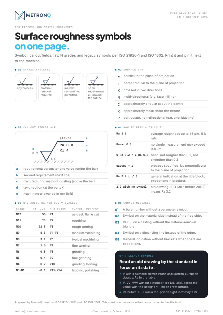
Surface roughness symbols - cheat sheet
Symbol variants, callout fields a-e, the 7 lay symbols, example callouts, N grades with old ∇ classes, common mistakes and legacy symbols. A4, portrait.
Sources
- 1.ISO 21920-1:2021 (indication of surface texture on drawings; replaces ISO 1302:2002)
- 2.ISO 1302:2002 (callouts on older drawings)
- 3.EN ISO 4287 (profile parameters Ra, Rz)
- 4.ISO 4288 (rules for comparing results with limits, the 16% and max rules)
- 5.T. Dobrzański, "Rysunek techniczny maszynowy", WNT (drawing callout practice).
- 6.ISO 15787:2016 (presentation of heat-treated parts on drawings)
- 7.DIN 3141 (former German surface symbols, withdrawn)
Read next
Automatic CNC machining quotes
Priced from the 3D model or the drawing, on your machines and your rates. You just approve it. 14 days free, no card.
Create a free account