IT Tolerance Grades: How ISO 286 Works

An IT tolerance grade defines how wide the tolerance zone of a dimension is: the lower the number, the narrower the zone and the more accurate the machining. The ISO 286 system has 20 grades, from IT01 to IT18, and the tolerance value in each grade grows with the nominal size. In this article we explain where the IT values come from, how the grade combines with the position of the tolerance zone, how to choose it for the function of a part and which grade a given machining method achieves.
IT tolerance grades: what they are and how ISO 286 works
An IT tolerance grade (International Tolerance grade) is the width of the tolerance zone expressed as a number. ISO 286-1 defines 20 grades: IT01, IT0 and IT1 to IT18. For a given size each grade is wider than the one before, and the same grade gives a larger tolerance on a larger diameter, because achievable accuracy falls as size grows.
The IT grade does not say where the tolerance zone lies, only how wide it is. Its position relative to the nominal size is set by a letter, the fundamental deviation, described below. Only the letter and number together, for example H7 or g6, form a complete tolerance class in the sense of the standard.
The same logic applies to holes and shafts, and the IT values are shared by both: IT7 at Ø25 is always 21 µm, whether it is an H7 hole, an h7 shaft or a k7 shaft.
Tolerance, deviations and limits of size
The tolerance is the difference between the upper and lower limit of size, and at the same time the difference between the upper and lower deviation:
where:
- - tolerance [µm],
- , - upper and lower deviation of a hole [µm] (for a shaft and ).
The nominal size is the value on the drawing from which deviations are measured. The upper limit of size is the nominal size plus the upper deviation, and the lower limit is the nominal size plus the lower deviation. An Ø25 H7 hole has deviations of +21 and 0 µm, so it is good if it measures from 25.000 to 25.021 mm.
Where IT values come from: the standard tolerance factor
IT values from IT5 to IT18 are derived from the standard tolerance factor , which grows with the cube root of the size. Each grade is a multiple of this factor: IT6 is 10 units, IT7 16, IT8 25, IT9 40, IT10 64 and IT11 100. Every five grades the tolerance grows tenfold.
The standard tolerance factor for sizes up to 500 mm:
where:
- - standard tolerance factor [µm],
- - geometric mean of the size range limits [mm], e.g. for the 18-30 mm range.
For the 18-30 mm range the geometric mean is 23.24 mm, the tolerance factor 1.307 µm and IT7 = 16 · 1.307 = 20.9 µm. The standard rounds this to 21 µm. For the 400-500 mm range the formula gives 62.2 µm and the table 63 µm. These differences are why only the values from the ISO 286-1 tables apply on the drawing and in inspection, not the result of the formula.
Table of IT5-IT11 values
The grades used most in machining are IT5-IT11. Below are their values in micrometres for size ranges up to 500 mm, according to ISO 286-1. Range limits read as "above ... up to and including ...", so Ø30 belongs to the 18-30 range and Ø30.01 already to 30-50.
| Size [mm] | IT5 | IT6 | IT7 | IT8 | IT9 | IT10 | IT11 |
|---|---|---|---|---|---|---|---|
| up to 3 | 4 | 6 | 10 | 14 | 25 | 40 | 60 |
| over 3 to 6 | 5 | 8 | 12 | 18 | 30 | 48 | 75 |
| over 6 to 10 | 6 | 9 | 15 | 22 | 36 | 58 | 90 |
| over 10 to 18 | 8 | 11 | 18 | 27 | 43 | 70 | 110 |
| over 18 to 30 | 9 | 13 | 21 | 33 | 52 | 84 | 130 |
| over 30 to 50 | 11 | 16 | 25 | 39 | 62 | 100 | 160 |
| over 50 to 80 | 13 | 19 | 30 | 46 | 74 | 120 | 190 |
| over 80 to 120 | 15 | 22 | 35 | 54 | 87 | 140 | 220 |
| over 120 to 180 | 18 | 25 | 40 | 63 | 100 | 160 | 250 |
| over 180 to 250 | 20 | 29 | 46 | 72 | 115 | 185 | 290 |
| over 250 to 315 | 23 | 32 | 52 | 81 | 130 | 210 | 320 |
| over 315 to 400 | 25 | 36 | 57 | 89 | 140 | 230 | 360 |
| over 400 to 500 | 27 | 40 | 63 | 97 | 155 | 250 | 400 |
You can calculate the deviations for a specific diameter and class, together with the limits of size, in the ISO 286 tolerance calculator.
Fundamental deviations: the position of the tolerance zone
The fundamental deviation is whichever of the two deviations lies closer to the zero line, and it sets the position of the tolerance zone. It is written as a letter: capital for holes (A-ZC), lower case for shafts (a-zc). The other deviation follows by adding or subtracting the IT value.
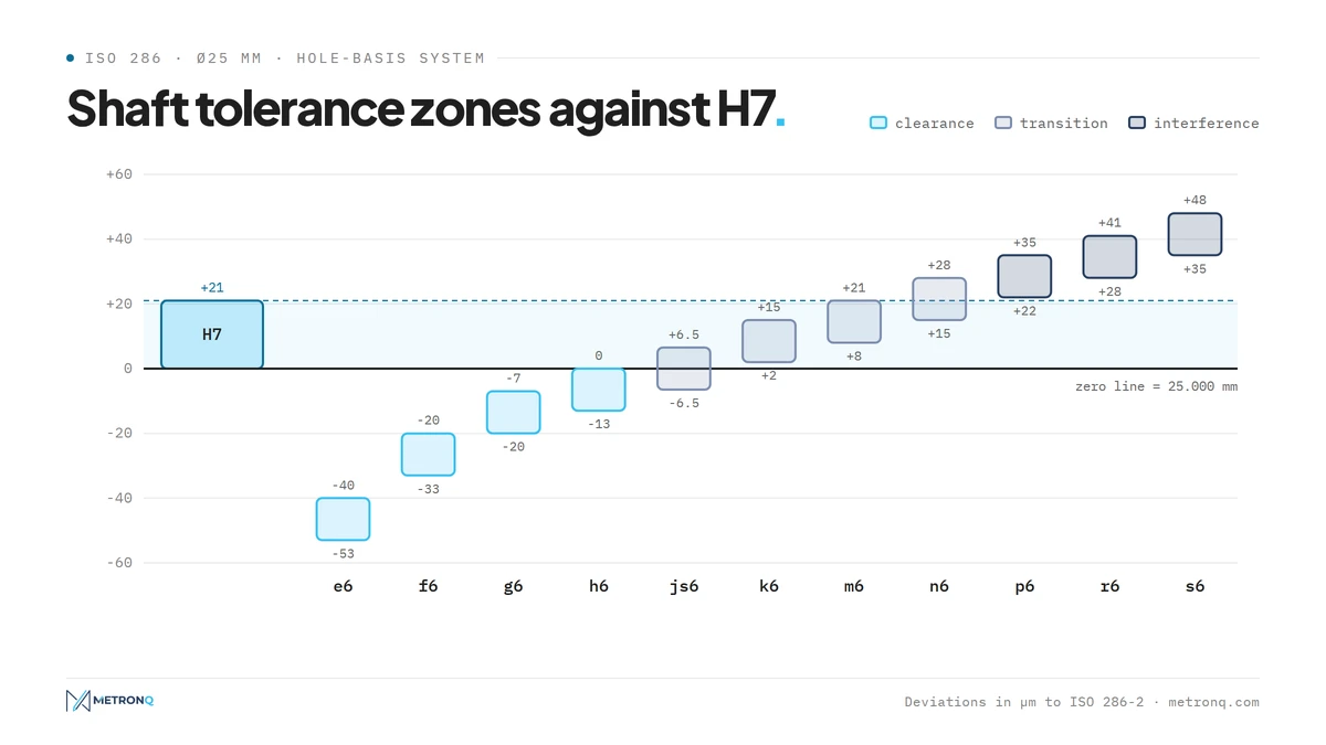
The letters H and h have a fundamental deviation of zero: an H hole starts at the nominal size and grows upwards, an h shaft ends at it and goes downwards. Shafts a to g are smaller than nominal, so with an H hole they give clearance. Shafts k to zc lie above the zero line and give interference, the more so the further down the alphabet. The js and JS classes are symmetrical: plus or minus half the IT value.
Holes mirror the shafts with the same letter, with one exception: for K, M, N holes up to IT8 and P to ZC holes up to IT7 the standard adds a correction , equal to the difference between the given grade and the grade one lower. This gives shaft-basis fits the same clearances and interferences as hole-basis fits. The correction is a common error in home-made tables.
How to choose the IT grade for a part's function
The IT grade is chosen for what a surface does in the assembly, not for what the machine can do. Surfaces that mate with bearings and bushings need IT5-IT7, ordinary joints IT8-IT11, while free dimensions sit in IT12 and coarser, usually covered by a general tolerance.
| IT grades | Typical application |
|---|---|
| IT01-IT4 | gauge blocks, gauges, measuring instrument parts |
| IT5-IT6 | rolling bearing seats, precision spindles, interference fits |
| IT7-IT8 | housing bores, bushings, gears on shafts, sliding fits |
| IT9-IT11 | keyways, loose joints, low-accuracy mating dimensions |
| IT12-IT18 | free dimensions, stock: bar, forgings, castings |
In practice a hole usually gets a grade one step coarser than the shaft (H7/g6, H7/k6, H8/f7), because a hole is harder to make and measure. Dimensions that touch nothing can use the ISO 2768 general tolerance, for example class m. Writing IT7 "just in case" does not improve the part, it only changes how it has to be made.
IT grades and the machining method
Each machining method has a range of IT grades it achieves economically, that is without slowing the process or adding passes. Drilling usually gives IT11-IT13, finish turning and milling IT8-IT9, precision turning and reaming IT7, and grinding IT5-IT6. Tighter grades need honing or lapping.
| Machining method | IT grades (guide) |
|---|---|
| roughing (turning, milling) | IT12-IT14 |
| drilling | IT11-IT13 |
| finish turning and milling | IT8-IT9 |
| reaming, precision boring, precision turning | IT7-IT8 |
| grinding | IT5-IT6 |
| honing, lapping | IT3-IT6 |
These are guide values for typical conditions. A rigid machine, short tool overhang and stable temperature push the limits down, while thin walls and long, slender parts push them up. How the IT grade translates into machining stages, from roughing to finishing, is covered in our guide to machining, and the typical sequence for a shaft with h6 journals in the machining process plan.
IT grades and machining cost
Every tighter IT grade raises the cost of a part, because it needs slower parameters, an extra finishing pass, often a separate operation and closer inspection. Going from IT9 to IT7 on a hole usually means extra reaming, and from IT7 to IT6 on a shaft usually grinding instead of turning.
That is why a quote depends not only on geometry but also on the list of surfaces with tight tolerances. In the shop panel the process engineer sees the time and price broken down by operation, so the cost of each tolerance in the model is visible at once. Which tolerances can be safely relaxed is covered in tolerances vs CNC machining cost.
How to specify and check a tolerance class
A tolerance class is written on the drawing as a symbol next to the dimension, for example Ø25 H7, numerically as Ø25 with deviations of +0.021 and 0, or both at once. The symbol is shorter and unambiguous for the process engineer, while the deviations in brackets make life easier for the operator at the machine.
For fits, ISO 286-1 recommends adding the envelope requirement, marked with the letter E in a circle (ISO 14405-1), which also limits form errors within the size tolerance. In series inspection, holes and shafts in IT6-IT8 are checked with limit gauges: the go side must enter and the no-go side must not.
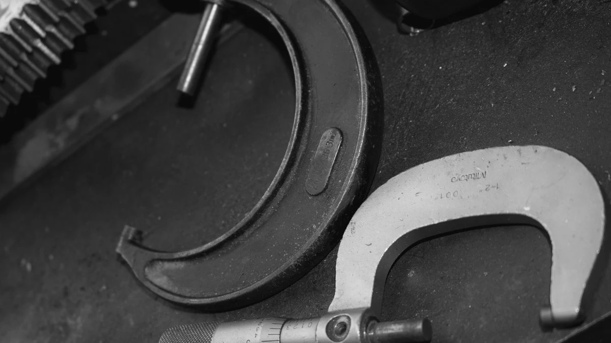
A measuring instrument should have an uncertainty of no more than about one tenth of the tolerance. For an Ø25 h6 shaft with a 13 µm tolerance a caliper with 0.02 mm resolution is not suitable; you need a micrometer or a dial indicator in a fixture. More on surface measurement is in our article on surface roughness.
Frequently asked questions about IT tolerance grades
What does IT7 tolerance grade mean?
IT7 is the seventh tolerance grade in ISO 286, equal to 16 standard tolerance units. At 25 mm diameter it gives a zone 21 µm wide, at 100 mm 35 µm. It is the typical grade for fitted holes (H7) and precision-turned surfaces, achievable by reaming, precision boring or careful turning.
How many tolerance grades does ISO 286 define?
ISO 286-1 defines 20 tolerance grades: IT01, IT0 and IT1 to IT18. Grades IT01-IT4 are for gauges and measuring instruments, IT5-IT11 for machine parts and fits, and IT12-IT18 for free dimensions and stock. In machining, grades IT5 to IT11 are by far the most common.
What is the difference between an IT grade and a fundamental deviation?
The IT grade sets the width of the tolerance zone, the fundamental deviation its position relative to the nominal size. In H7, the letter H is the fundamental deviation (lower deviation equal to zero) and the number 7 is the IT grade. Only the two together define the limits of size of a hole or shaft unambiguously.
Why does the tolerance grow with diameter?
Because manufacturing and measuring get harder with size: a larger part deforms more with temperature, and machine and instrument errors add up over a longer path. The tolerance factor grows roughly with the cube root of the diameter, which is why IT7 at Ø100 is only about 1.7 times wider than at Ø25.
What IT grade does CNC turning achieve?
Ordinary CNC finish turning gives IT8-IT9, and precision turning with in-process gauging and tool wear compensation IT7, on rigid machines even IT6. IT5 and tighter usually require grinding. Rough turning gives IT12-IT14 and only removes stock before finishing, so it is never the final operation on a toleranced surface.
How do I check the deviations for a specific diameter?
The quickest way is a tolerance calculator: enter the nominal size, choose hole or shaft, the letter and the IT grade, and you get the upper and lower deviation and the limits of size. The alternative is the ISO 286-2 tables. Calculating with the tolerance factor formula gives errors of 1-2 µm.
Sources
- 1.ISO 286-1:2010, Geometrical product specifications (GPS) - ISO code system for tolerances on linear sizes - Part 1: Basis of tolerances, deviations and fits
- 2.ISO 286-2:2010, Part 2: Tables of standard tolerance classes and limit deviations for holes and shafts
- 3.ISO 2768-1:1989, General tolerances - Tolerances for linear and angular dimensions
- 4.ISO 14405-1:2016, Geometrical product specifications (GPS) - Dimensional tolerancing - Linear sizes
- 5.Z. Osiński (ed.), "Podstawy konstrukcji maszyn", PWN (tolerances and fits)
- 6.M. Feld, "Technologia budowy maszyn", PWN (machining accuracy by method)
- 7.Sandvik Coromant, "Training Handbook: Metal Cutting Technology" (turning and boring accuracy)
Read next
Automatic CNC machining quotes
Priced from the 3D model or the drawing, on your machines and your rates. You just approve it. 14 days free, no card.
Create a free account