ISO Fit Tolerance Chart and Fit Types
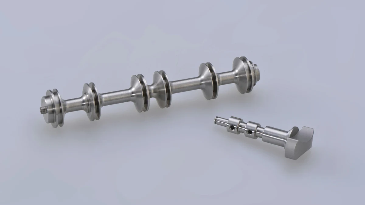
A fit describes how a hole and a shaft with the same nominal size behave once assembled: with clearance, with interference or, depending on the actual sizes, with either. It follows from the position of the two tolerance zones defined in ISO 286. In this article you will find the three fit types, the hole basis system, a fit tolerance chart with clearances and interferences, and how to choose a fit for the function of the joint.
What a fit is: clearance and interference
A fit defines how a hole and a shaft with the same nominal size work together: whether the shaft turns and slides freely, sits without play, or has to be pressed in. It is written as a pair of tolerance classes, for example Ø25 H7/g6, with the hole above the line and the shaft below it.
The type of fit depends on the difference between the limits of size of the hole and the shaft. Maximum clearance occurs with the largest hole and the smallest shaft, minimum clearance with the smallest hole and the largest shaft:
where:
- , - maximum and minimum clearance [µm],
- , - upper and lower deviation of the hole [µm],
- , - upper and lower deviation of the shaft [µm].
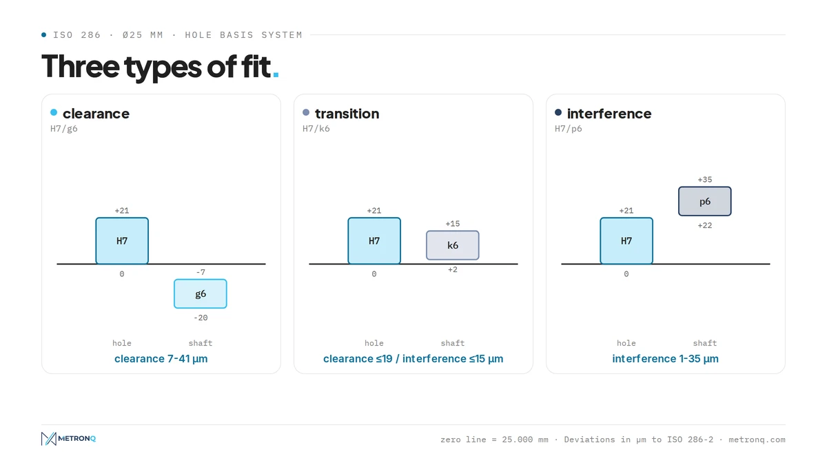
A negative result means interference. At Ø25 H7/g6 the hole has deviations of +21 and 0 µm and the shaft -7 and -20 µm, so the clearance ranges from 7 to 41 µm. You can calculate the fit for any diameter and pair of classes in the tolerance calculator, on the Fit tab.
Clearance fit, transition fit and interference fit
ISO 286 distinguishes three fit types. A clearance fit always has clearance, because the hole's tolerance zone lies entirely above the shaft's. An interference fit always has interference. In a transition fit the zones overlap, so depending on the actual sizes the result is a small clearance or a small interference.
Clearance fits: running and sliding
Clearance fits are used where parts must rotate or slide relative to each other. In the hole basis system they are formed with shafts a to h: the further the letter from h, the larger the clearance. The common names are close running (H7/f7), sliding (H7/g6) and locational clearance (H7/h6).
The locational clearance fit H7/h6 has a minimum clearance of zero. Parts assemble by hand but without noticeable play, which makes it typical for located parts that are rarely moved, such as change gears, locating bushings and spacer rings. For rotation under load H7/g6 or H7/f7 is better, because it leaves room for the lubricating film.
Transition fits
Transition fits are formed with shafts js, k, m and n and an H hole. They locate parts accurately but do not transmit torque without an extra element, which is why a gear on an H7/k6 shaft usually also has a key. Assembly uses light tapping or a press, and the joint can be taken apart without damage.
The tighter transition fit H7/n6 is close to an interference fit: at Ø25 it leaves at most 6 µm of clearance, while the interference reaches 28 µm. It is used where a part must stay put under vibration but still be removable for service.
Interference fits: press and shrink fits
Interference fits are formed with shafts p to zc and an H hole. There is always interference, so the joint transmits torque and axial force without a key, and taking it apart usually damages the surfaces. H7/p6 is the locational interference fit, H7/s6 the medium drive fit, and H7/u6 the force fit.
With large interference, such as H7/s6, parts are shrink-fitted: the hole is heated, for example a wheel hub to 150-250°C, or the shaft is cooled with dry ice or liquid nitrogen. The H7/p6 press fit can still be assembled cold with a press, with lubricated surfaces.
Hole basis system and shaft basis system
In the hole basis system every hole has the fundamental deviation H, and the fit type is set by the shaft. It is the standard in machine building, because an H7 hole is made with a reamer or boring tool of fixed size and checked with one gauge, while a shaft is easy to measure and turn to any class.
This way a shop needs one Ø25 H7 reamer and one plug gauge, and gets clearance, transition and interference fits through the shaft size alone. In the shaft basis system each fit would need a different reamer and a different gauge.
The shaft basis system (h shaft, holes with different letters) makes sense in three cases: when several parts with different fits sit on one plain shaft, when the shaft is drawn bar in h9 or h11 that will not be machined, and for the outer rings of rolling bearings, whose size is set by the manufacturer.
Equivalent fits: H7/p6 and P7/h6
Fits with the same letters on swapped sides are equivalent: H7/p6 gives the same clearances and interferences as P7/h6. The standard achieves this with a correction added to the deviations of K, M, N and P to ZC holes in the fine grades. The details of this correction and how the grades are built are covered in our article on IT tolerance grades.
Fit tolerance chart: ISO fits for Ø25
The fit tolerance chart below lists the most common pairs in the hole basis system for a 25 mm diameter, that is for the whole size range above 18 up to 30 mm in ISO 286-2. It gives the hole and shaft deviations, the resulting clearance or interference, the fit type, the common name and typical applications.
| Fit | Hole [µm] | Shaft [µm] | Clearance / interference [µm] | Type | Common name | Typical application |
|---|---|---|---|---|---|---|
| H7/f7 | +21 / 0 | -20 / -41 | clearance 20-62 | clearance | close running | plain bearings, rotating shafts |
| H7/g6 | +21 / 0 | -7 / -20 | clearance 7-41 | clearance | sliding | precise guides, slides, pins |
| H7/h6 | +21 / 0 | 0 / -13 | clearance 0-34 | clearance | locational clearance | located and sliding parts, change gears |
| H7/k6 | +21 / 0 | +15 / +2 | clearance up to 19 / interference up to 15 | transition | locational transition | keyed gears, couplings, pulleys |
| H7/n6 | +21 / 0 | +28 / +15 | clearance up to 6 / interference up to 28 | transition | locational transition (tight) | keyed hubs, bushings, gear rims |
| H7/p6 | +21 / 0 | +35 / +22 | interference 1-35 | interference | locational interference | pressed bushings, ring gears |
| H7/s6 | +21 / 0 | +48 / +35 | interference 14-48 | interference | medium drive | torque without a key, shrink fits |
The common names follow the ISO preferred fits list known from ANSI B4.2 and vary slightly between sources, so the drawing always uses the ISO symbol. The h7 fit and any other pair for your own diameter can be calculated in the ISO 286 tolerance calculator.
Fit chart for other sizes
Clearances and interferences grow with size, because the IT value and the fundamental deviations increase with the diameter. Below are the four most common fits for ranges from 3 to 120 mm (in micrometres, valid for the whole range).
| Size [mm] | H7/g6 | H7/h6 | H7/k6 | H7/p6 |
|---|---|---|---|---|
| over 3 to 6 | clearance 4-24 | clearance 0-20 | clearance 11 / interference 9 | interference 0-20 |
| over 6 to 10 | clearance 5-29 | clearance 0-24 | clearance 14 / interference 10 | interference 0-24 |
| over 10 to 18 | clearance 6-35 | clearance 0-29 | clearance 17 / interference 12 | interference 0-29 |
| over 18 to 30 | clearance 7-41 | clearance 0-34 | clearance 19 / interference 15 | interference 1-35 |
| over 30 to 50 | clearance 9-50 | clearance 0-41 | clearance 23 / interference 18 | interference 1-42 |
| over 50 to 80 | clearance 10-59 | clearance 0-49 | clearance 28 / interference 21 | interference 2-51 |
| over 80 to 120 | clearance 12-69 | clearance 0-57 | clearance 32 / interference 25 | interference 2-59 |
How to choose an H7 fit for the function of the joint
A fit is chosen for what the joint has to do: rotate, slide, only locate accurately, or transmit torque. First you pick the fit type (clearance, transition, interference), then the specific shaft to go with the H7 hole, and finally match the IT grade to the required accuracy and the machining method.
| Function of the joint | Typical fit | Notes |
|---|---|---|
| rotation with large clearance, high temperature | H8/e8, H8/f7 | bushings, plain bearings |
| precise rotation or sliding | H7/g6 | guides, slides, pins |
| location with hand assembly | H7/h6 | change gears, locating bushings |
| accurate location, torque through a key | H7/k6, H7/n6 | gears, couplings, pulleys |
| permanent seat, press assembly | H7/p6, H7/r6 | bushings, dowel pins, rims |
| torque without a key | H7/s6, H7/u6 | shrink fits |
Fits for rolling bearings
A rolling bearing fit is chosen from the bearing manufacturer's catalogue, because it depends on the direction and size of the load. With a rotating shaft and a stationary housing the inner ring sits tight, usually on a k5, k6 or m6 shaft, and the outer ring looser, in an H7 or J7 housing.
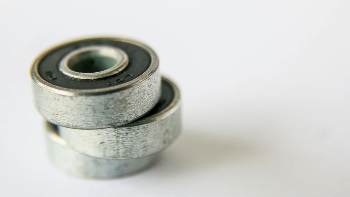
Bearing rings have their own narrow manufacturing tolerances, so the same letters give different clearances at a bearing than in the ISO fit chart. A k6 journal for a 6205 bearing (Ø25) therefore always gives interference, not a transition fit as in the H7/k6 pair. SKF and Schaeffler recommendations give the fit for a given diameter and load.
Temperature, material and roughness
The clearances and interferences in the chart apply at 20°C and to steel parts. An aluminium hub on a steel shaft loses interference when it warms up, because aluminium expands almost twice as much as steel. Roughness matters too in interference fits: the peaks are flattened during assembly, so the effective interference is smaller than calculated.
That is why press-fit surfaces are usually specified at or better. How to read roughness requirements on a drawing is explained in our article on surface roughness.
Fits and machining cost
A tighter fit means a finer IT grade, and a finer grade means longer finishing and closer inspection. An H7 hole usually needs reaming or finish boring, and an h6 shaft grinding or very careful turning. Every such surface adds an operation, a tool and measuring time.
In practice an H7 hole is drilled and reamed or bored, and a bearing seat is ground or precision-turned, as described in our article on finish machining. Which IT grade a given machine holds without extra operations depends on its condition and calibration, which is why in MetronQ the shop enters its own machines and calibration.
A fit on the drawing without a function, such as H7 on clearance holes for bolts, raises the price of the part with no benefit. Which tolerances can be safely relaxed is covered in tolerances vs CNC machining cost.
Frequently asked questions about fits
What does an H7/g6 fit mean?
H7/g6 is a clearance fit in the hole basis system: a hole in class H7 and a shaft in class g6. At 25 mm diameter the clearance ranges from 7 to 41 µm. It is known as a sliding fit and is used for precise guides, pins and slides that must move without noticeable play.
Which fit should I use for a bearing?
With a rotating shaft the inner ring of a bearing usually sits on a k5, k6 or m6 shaft, and the outer ring in an H7 or J7 housing. The exact choice depends on load and diameter, so it is always worth checking the fit table in the bearing manufacturer's catalogue, such as SKF or Schaeffler.
What is the difference between a clearance fit and a locational clearance fit?
A locational clearance fit is a special case of a clearance fit with a minimum clearance of zero, for example H7/h6. Parts assemble by hand but without noticeable play. Other clearance fits, such as H7/g6 or H7/f7, always leave clearance, which is needed for free rotation and a lubricating film.
What is an interference fit?
An interference fit is a fit in which the shaft is always larger than the hole, so there is interference after assembly. Such a joint transmits torque and axial force without a key. Examples are H7/p6, assembled with a press, and H7/s6, shrink-fitted by heating the hole or cooling the shaft.
When is the shaft basis system used?
The shaft basis system is used when several parts with different fits sit on one plain shaft, when the shaft is unmachined drawn bar in an h tolerance, and for the outer rings of rolling bearings. In all other cases the hole basis system with H holes is cheaper to manufacture and inspect.
How do I calculate the clearance and interference of a fit?
Maximum clearance is the hole's upper deviation minus the shaft's lower deviation, and minimum clearance is the hole's lower deviation minus the shaft's upper deviation. A negative result means interference. Two positive results give a clearance fit, two negative an interference fit, and mixed signs a transition fit.
Sources
- 1.ISO 286-1:2010, Geometrical product specifications (GPS) - ISO code system for tolerances on linear sizes - Part 1: Basis of tolerances, deviations and fits
- 2.ISO 286-2:2010, Part 2: Tables of standard tolerance classes and limit deviations for holes and shafts
- 3.ANSI B4.2-1978 (R2020), Preferred Metric Limits and Fits
- 4.SKF, "Rolling bearings" - general catalogue (shaft and housing fits)
- 5.Z. Osiński (ed.), "Podstawy konstrukcji maszyn", PWN (selection of fits)
Read next
Automatic CNC machining quotes
Priced from the 3D model or the drawing, on your machines and your rates. You just approve it. 14 days free, no card.
Create a free account