Flatness Tolerance: Symbol, Zone and Measurement

Flatness tolerance is a form tolerance that states how far an actual surface may depart from an ideal plane. On a drawing it is given in a feature control frame with a parallelogram symbol and a value in millimetres, e.g. 0.05. The tolerance zone is the space between two planes that distance apart, and the whole surface must fit inside it.
Flatness: definition and tolerance zone
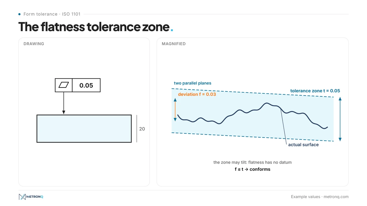
Flatness describes how far a surface departs from a common plane. Under ISO 1101 the actual surface must lie between two parallel planes separated by the value in the frame. There is no datum and no dimension involved, only form. Such a flat surface may be tilted in any direction and still conform.
An ideal plane exists only in the CAD model. Every milled or ground surface has bumps, hollows and twist. The flatness deviation of a surface is the smallest distance between two planes that enclose the whole measured surface. If the deviation is 0.03 mm and the drawing says 0.05, the surface is good.
Surface flatness does not depend on orientation: a plate can lean a few degrees relative to a datum and still meet the requirement in the frame. Other tolerances, described below, control orientation. A flat surface with a flatness frame is typically a mating face, a sealing face, a slideway or the base of a housing.
Geometric tolerances: form and location
A geometric tolerance limits the form, orientation, location or run-out of a feature, i.e. what size alone does not describe. ISO 1101, published by the International Organization for Standardization (ISO), divides them into four groups. Flatness belongs to the form group and, like every tolerance in that group, never has a datum.
Size and geometry are independent, following the independency principle of ISO 8015. A plate thickness of 20 ±0.1 says nothing about form, because thickness is measured locally between two points. A plate can therefore be within its thickness tolerance and still be bent like a boat. How to work out size deviations is explained in our article on dimensional tolerance.
Form tolerance: flatness, straightness, roundness, cylindricity
A form tolerance applies to a single feature and compares it with its own ideal shape, without a datum. Here the ideal shape is a plane. The group includes straightness, flatness, roundness and cylindricity, plus line profile and surface profile when given without datums. Each has a differently shaped tolerance zone.
Every feature has its ideal shape defined on the drawing, and the frame states how far the actual feature may depart from it. ISO 1101 and the detailed standards, such as ISO 12781 for flatness, define both the tolerance zone and how the result is evaluated. For straightness the deviations of an actual line are assessed, here the whole surface.
Form tolerances are worth applying where function depends on geometry: sealing, contact, guiding. The standards do not suggest values, so the zone is chosen to suit the function and the machining capability. On non-functional surfaces it is better to leave the frame out altogether, because every frame means another measurement; the general tolerance note in the title block covers the rest.
Location, orientation and run-out tolerances
A location tolerance limits where a feature sits relative to datums, and an orientation tolerance limits its tilt. Orientation covers parallelism, perpendicularity and angularity; location covers position, coaxiality and symmetry. They refer to a datum, which appears in the frame, and that is what separates them from the form group.
Position tolerance is most often used for hole axes: the cylindrical tolerance zone is a cylinder whose diameter equals the value in the frame, with its axis located by theoretically exact dimensions. The cylindrical zone is shown by the Ø sign before the value, and the hole axis must stay inside it along its full length. The actual position deviation is the distance of the hole axis from its ideal location; reports often give it as a diameter, i.e. doubled.
The permissible deviation in a position tolerance is half the zone diameter, because the axis may move away from nominal in any direction. With position Ø 0.1 the permissible deviation is 0.05 mm radially. If the axis moves further, the tolerance is exceeded and the hole may not line up with its mating hole.
Flatness versus form and location tolerances: what controls what
The four groups form a hierarchy: an orientation tolerance also limits form, and a location tolerance limits orientation and form. Parallelism of 0.05 to datum A automatically limits the form of that surface to 0.05, because its zone is again two parallel planes, only oriented parallel to the datum.
A separate form frame is therefore given only when it must be tighter than the parallelism, for example parallelism 0.05 and flatness 0.02. Two mutually parallel mating faces of a housing often carry two frames: parallelism to the datum and a second, tighter one without a datum. Parallel faces without a second frame have their form limited by parallelism alone.
Mutually parallel faces are measured from the datum, and faces with their own form frame are additionally checked on a surface plate. When two parallel faces have different functions, such as a mating face and a mounting face, give them different values, because a tight tolerance on both raises cost with no benefit.
Older drawings made to former national standards, such as older Polish PN standards, sometimes use combined tolerances, for example a combined perpendicularity and flatness deviation: each surface must lie between two planes perpendicular to the datum. In the ISO system a plain orientation tolerance does the same, because its zone covers form and tilt at once.
Geometric tolerance symbols and technical drawings
The geometric tolerance symbols are the 14 characters of ISO 1101 that a technical drawing places in a feature control frame. Flatness is a parallelogram, straightness a line, roundness a circle, parallelism two strokes and position a circle with a cross. A frame has two compartments for features without a datum and three or more for tolerances with datums.
| Group | Characteristic | Datum |
|---|---|---|
| form | straightness, flatness, roundness, cylindricity | no |
| form, orientation or location | line profile, surface profile | depends on the callout |
| orientation | parallelism, perpendicularity, angularity | yes |
| location | position, coaxiality, symmetry | yes |
| run-out | circular run-out, total run-out | yes |
Location symbols normally stand with a datum letter in the next compartment, and the datum feature is marked on the drawing with a datum triangle and a letter. Location symbols without a datum letter are rare, for example for the relative position of a hole pattern. A datum letter that does not exist on the drawing makes the callout ambiguous, because nobody knows where to measure from.
A flatness frame looks like this: a parallelogram, the value 0.05 and nothing else. The leader arrow points to the surface, or to its dimension line when the median plane is meant. Form symbols always stand in the first compartment of the frame.
The symbol is only half of the callout. What quality control checks also depends on the stated tolerance value and any modifiers, for example a note that the requirement applies only to a selected area of the surface.
Tolerance zone: definition, shape and size
ISO 1101 defines the tolerance zone simply: it is the region in which the actual feature must lie. The shape of the zone depends on the characteristic and on the callout in the frame. For flatness it is the space between two planes, for the position of a hole axis a cylinder, for roundness an annulus.
Many textbooks call it a band or layer: the flatness zone is a layer as thick as the value in the frame. The size of the zone depends on that value, and for position the location of the zone also depends on the boxed dimensions that fix where the cylinder axis lies.
The zone must contain every point of the actual surface, not their average. A single protruding point is enough to make the feature nonconforming even if the rest is perfect. The surface must fit within the zone over its full length and width, including local hollows, so there must be enough measuring points.
The flatness zone is not fixed in space: both planes may shift and tilt freely as long as the distance between them equals the value in the frame. The zone floats with the surface. The zone is fixed only in tolerances with datums, such as parallelism or position.
Example: for a plane with a flatness zone of 0.05 mm, the zone is a layer 0.05 mm thick, placed so that it contains the whole surface. For a hole position of Ø 0.1, the zone is a cylinder of Ø 0.1 mm. This simple zone shape is why flatness is quicker to measure than tolerances with datums.
Graded tolerance values: what to specify
Graded tolerance values are a series from which the designer chooses according to surface size and functional requirements. When the drawing gives no frame, the values and classes come from ISO 2768-2: classes H, K and L, in which the value grows with the length of the surface.
| Longest side of the surface [mm] | H | K | L |
|---|---|---|---|
| up to 10 | 0.02 | 0.05 | 0.1 |
| over 10 to 30 | 0.05 | 0.1 | 0.2 |
| over 30 to 100 | 0.1 | 0.2 | 0.4 |
| over 100 to 300 | 0.2 | 0.4 | 0.8 |
| over 300 to 1000 | 0.3 | 0.6 | 1.2 |
| over 1000 to 3000 | 0.4 | 0.8 | 1.6 |
Values are in millimetres. An "ISO 2768-mK" note in the title block therefore gives a 200 mm long plate a flatness of 0.4 mm, which is rarely enough for a sealing face. Part 2 of the standard was withdrawn in 2021 but is still common on drawings; see our article on ISO 2768 general tolerances. Older national standards, such as the Polish PN-80/M-02138, gave these values in accuracy series.
A tolerance in a frame always takes precedence over the table. For mating and sealing faces the designer chooses the value, guided by neighbouring tolerances, sealing requirements and machining capability. A designer who knows the assembly requirements and the cost of grinding rarely specifies a tighter value than needed.
Profile of a surface and its deviation
The surface profile tolerance, called "shape of a specified surface" in older Polish standards, controls a surface defined by theoretically exact dimensions. Its zone lies on both sides of the ideal surface and is as wide as the value in the frame. It is used where the nominal surface is curved, not flat.
The surface profile tolerance checks all points of the indicated surface against the model. The deviation is the largest distance of a point of the actual surface from the ideal surface, measured normal to it. With datums the surface profile tolerance also controls location; without datums it controls only the shape of the indicated surface.
For lines the equivalent is the line profile tolerance. Its deviation is the largest departure of the contour in a given section, and comparing several sections shows whether an error is local or repeats along the whole length. In practice the surface profile tolerance is the most versatile callout: it covers planes, cylinders and freeform surfaces, which are checked on a coordinate measuring machine against the CAD model.
The specified surface and theoretically exact dimensions
The specified surface is the nominal surface defined by theoretically exact dimensions, shown in rectangular frames without tolerances. These dimensions have no deviations because they only fix where the ideal surface lies. The whole tolerance is carried by the profile frame at the surface, and the boxed dimensions only locate it.
The requirements for the specified surface are therefore read from two places: the boxed dimensions and the value in the feature control frame. The inspector compares the surface with the model: for every point the deviation goes into a report that lists the deviations, the requirements and the decision. The deviation has a sign in the report: plus outside the material, minus inside.
A CMM report lists deviations, requirements and the result point by point, and the same for line profiles section by section. When the zone is exceeded at a single point only, it is usually a local defect, such as a burr, and not an error in the whole geometry.
Measuring flatness: method and accuracy
Measuring flatness means collecting the heights of many points on the measured surface and finding two planes that enclose them all as tightly as possible. The measuring method is chosen to suit the tolerance value, the surface size and the number of parts, because those three decide the required accuracy and the measuring time.
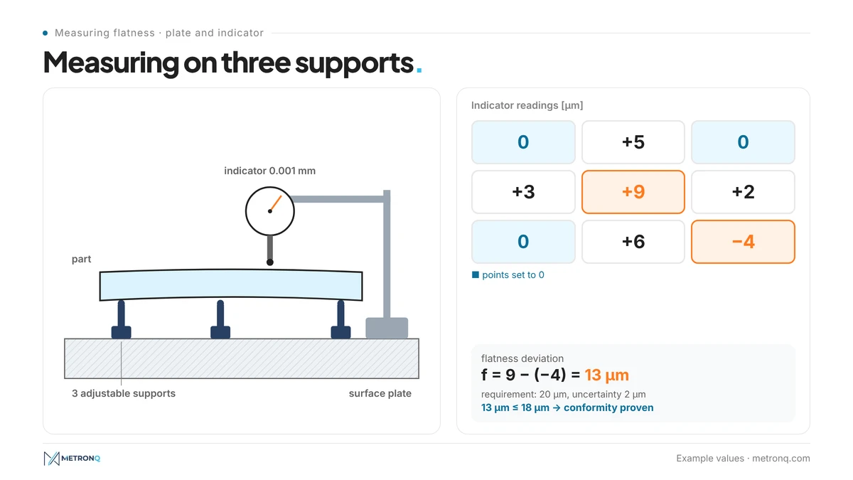
Precise flatness measurement of small and medium parts is done on a surface plate with a dial indicator. The part stands on three adjustable supports, three widely spaced points are set to zero, and the indicator is then moved over a grid of points. The deviation is the difference between the highest and the lowest reading:
where:
- - flatness deviation relative to the plane through three points [mm],
- - highest indicator reading [mm],
- - lowest indicator reading [mm].
Without levelling three points, an indicator on a surface plate shows parallelism to the plate, not form. This is the most common shop-floor mistake, because the result is inflated by the tilt of the part. Thin parts also need support without clamping force, otherwise they sag under their own weight, and a part held in the hands warms up and distorts.
Measuring methods, accuracy and applications
The measuring method should be chosen by the ratio of its uncertainty to the tolerance. Method, accuracy and measuring time are linked: a straightedge and feeler gauge are fast but coarse, a plate with an indicator gives micrometres, an optical flat tenths of a micrometre, and a coordinate measuring machine a complete map of the surface.
| Method and accuracy | Application | Notes |
|---|---|---|
| straightedge and feeler gauge | quick check, wide tolerances | checks lines, not the whole surface |
| surface plate, supports, indicator | parts up to a few hundred mm | three points must be levelled |
| optical flat | lapped and polished surfaces | interference fringes, fractions of a micrometre |
| electronic level, autocollimator | surface plates, machine beds | measurement along grid lines |
| coordinate measuring machine | full map, report | result depends on the number of points |
Lapped parts are checked with an optical flat: it is laid on the surface and the fringes are counted in monochromatic light. Each fringe equals half a wavelength:
where:
- - number of fringes of deviation [-],
- - wavelength of light, e.g. approx. 0.59 µm [µm].
Two fringes therefore correspond to about 0.59 µm. Large surfaces several metres long are measured with an electronic level or an autocollimator: angles are measured over successive steps and summed into a profile. A machine bed needs a different method, accuracy and number of points than a small mating face.
Minimum zone method and the reference plane
The minimum zone method searches for the two closest planes that enclose all points of the measured surface. It is the default evaluation in ISO 1101 and gives the smallest possible deviation. The least squares method is faster but gives a result that is equal or larger.
On a coordinate measuring machine the software fits an ideal reference plane to the collected points, and the result is the sum of the distances of the highest and lowest points from it. The least squares reference plane lies "in the middle" of the points, while the minimum zone touches the extremes. When the result is close to the limit, it is worth recalculating it with the minimum zone method.
The plane the result refers to need not be parallel to the table or to any datum. The height of each point is measured from it, not from the surface plate. The number and layout of points matter: a sparse grid misses hollows on the measured part, so the deviation may be understated.
Accuracy of flatness measurement and uncertainty
The accuracy of flatness measurement depends on the plate, the indicator, the support and the temperature. Every measurement result has an uncertainty, so a number in a report is not enough on its own. A practical rule says the instrument uncertainty should be several times smaller than the tolerance, ideally about ten times, so that it does not eat up the zone.
The permissible uncertainty follows from the flatness requirement. For 0.02 mm a dial indicator with 0.01 mm graduation is not enough; an indicator with 0.001 mm graduation and a higher-grade plate are needed. Under ISO 14253-1 the supplier proves conformity only when the deviation lies within the tolerance reduced by the uncertainty.
Example (example values): a 200 × 120 mm plate, a flatness requirement of 0.02 mm, a grid of 9 points, extreme readings of +0.009 and -0.004 mm. The flatness deviation is 0.009 - (-0.004) = 0.013 mm. With an uncertainty of 0.002 mm, 0.013 mm is smaller than 0.018 mm, so conformity with the requirement is proven.
If the deviation were 0.019 mm with the same requirement, the result would fall in the uncertainty range, and neither supplier nor customer could decide conformity without a more accurate method.
Instrument calibration
Instrument calibration compares an instrument's readings with a standard of known uncertainty and results in a certificate with corrections. For flatness measurement the surface plate, the indicators and the coordinate measuring machine are calibrated first, because every error in these instruments goes straight into the result.
A granite surface plate is checked with an electronic level or an autocollimator along grid lines, because its working surface also deviates from a plane. A coordinate measuring machine is verified to ISO 10360, and dial indicators on an indicator tester. The calibration interval is set by the company according to how intensively the instrument is used and the accuracy required.
Quality control: measurement result versus drawing requirements
Quality control of flatness ends with a simple decision: the deviation is either inside the tolerance zone or not. For that decision to be reliable you need to know how the result was obtained: which method, how many points and what uncertainty. Quality control without a documented method is just a number.
Repeatability matters in quality control. The same parts checked by two people should give similar results; differences usually come from a different grid of points or a different setup. That is why an inspection instruction states the number of points, the evaluation method, the instrument and which part of the batch is the sample.
Checking surface flatness starts with cleaning the part and the plate and letting temperatures equalise. A part just taken off the machine is warmer and may be slightly bent. A result that survives a complaint can only be obtained on a clean surface, at a stable temperature and with a documented method.
Quality control also compares parts from the same batch with each other. When all measured parts have a similar shape of deviation, for example all are concave, the cause lies in the process, not in a random error. A part with a different type of deviation points rather to damage or a measuring mistake.
Flatness of a datum surface and the datum feature
A surface that serves as a datum for other tolerances needs good form itself. If the datum feature is convex, the part rocks on the plate, and every tolerance referred to it is measured from a random setup. That is why datum A often carries a flatness frame.
The datum's flatness is often several times tighter than the tolerances measured from it, for example datum flatness 0.01 mm with parallelism 0.05 mm. The datum feature should also be accessible for measurement and for clamping on the machine, and on a casting or a large plate it is often replaced by datum targets.
A datum target, as defined in ISO 5459, is a point of contact between the part and the measuring or clamping fixture. Three datum targets establish a datum plane on a rough surface where a full datum feature would be unstable. A target point is marked on the drawing with a cross, with a divided circle next to it holding the letter and number.
Datum targets are spaced as far apart as possible so that the datum plane is stable. Each target should be the same in machining and in inspection, otherwise the inspection result does not reflect how the part sat on the machine. The ideal reference plane then passes through the three targets.
How machining affects flatness and cost
Flatness after machining depends on part stiffness, clamping, residual stresses in the material and tool setup. A thin plate clamped in a vice deforms, springs back when released, and a surface that was flat on the machine is no longer flat once removed. Face milling with a slightly tilted spindle produces a slightly concave surface.
Rolled material contains residual stresses that are released as material is removed, so plates with a tight tolerance are machined in several setups, with turning over and stress relieving. According to the Manufacturing Process Selection Handbook, fine grinding achieves flatness of about 20 µm per metre, and lapping follows grinding when precision surfaces are needed, usually removing only 0.005-0.01 mm. Each of these is an extra operation, setup and measurement.
Every such operation has its own time and cost, which show up in the quote. In MetronQ's shop panel the price of a part is broken down by operation, so the process engineer immediately sees what the extra grinding for a tight flatness costs. We cover the link between tolerances and price in more detail in our article on tolerances and CNC machining cost.
Frequently asked questions about flatness and its measurement
How does flatness differ from a surface profile tolerance?
Flatness applies only to nominally flat surfaces and has no datum; its zone is two planes separated by the value in the frame. A surface profile tolerance applies to any surface defined by theoretically exact dimensions and may have datums. Flatness is therefore a special, simpler case of the profile tolerance.
How do you choose a flatness measuring method and what accuracy can it give?
The method is chosen to suit the tolerance: the uncertainty should be several to ten times smaller than the tolerance value. For 0.1 mm a plate and an indicator with 0.01 mm graduation are enough, for 0.01 mm an indicator with 0.001 mm graduation or a CMM, and for fractions of a micrometre an optical flat and interference fringes.
How do you check the flatness of a flat surface without a CMM?
Place the part on a surface plate on three supports, set three widely spaced points to the same height and move the indicator over a grid. The flatness deviation is the difference between the extreme readings. The result is always equal to or larger than the one given by the minimum zone method.
How often do quality control instruments need calibration?
The company sets the interval in its quality system, depending on how intensively the instrument is used, the working conditions and the accuracy required. The surface plate, indicators and CMM are calibrated periodically in an accredited laboratory or in-house against standards with a valid certificate. After an instrument is dropped or repaired, calibration is needed immediately.
What is a form tolerance and when should form and location tolerances be used?
Form tolerance is the group covering flatness, straightness, roundness and cylindricity. It is applied when function depends on the geometry of a single surface, for example sealing. Form and location tolerances are combined when the orientation relative to datums also matters, for example the parallelism of two mating faces.
How should combined flatness on older drawings be read?
Older Polish drawings sometimes contain combined tolerances, for example a combined parallelism and flatness deviation. They mean that the surface must lie between two planes oriented relative to a datum. In ISO 1101 the same effect comes from an ordinary parallelism tolerance, which by definition also limits the form of that surface.
Sources
- 1.ISO 1101:2017, Geometrical product specifications (GPS) - Geometrical tolerancing - Tolerances of form, orientation, location and run-out
- 2.ISO 12781-1:2011, Geometrical product specifications (GPS) - Flatness - Part 1: Vocabulary and parameters of flatness
- 3.ISO 2768-2:1989, General tolerances - Part 2: Geometrical tolerances for features without individual tolerance indications (withdrawn 2021)
- 4.ISO 8015:2011, Geometrical product specifications (GPS) - Fundamentals - Concepts, principles and rules
- 5.ISO 5459:2011, Geometrical product specifications (GPS) - Geometrical tolerancing - Datums and datum systems
- 6.ISO 14253-1:2017, Inspection by measurement of workpieces and measuring equipment - Part 1: Decision rules for verifying conformity or nonconformity with specifications
- 7.ISO 10360-2:2009, Acceptance and reverification tests for coordinate measuring systems (CMS) - Part 2: CMMs used for measuring linear dimensions
- 8.K. G. Swift, J. D. Booker, "Manufacturing Process Selection Handbook", Butterworth-Heinemann 2013, chapter 6 (grinding, lapping)
Read next
Automatic CNC machining quotes
Priced from the 3D model or the drawing, on your machines and your rates. You just approve it. 8 free quotes to start and 1 every month, no card.
Create a free account