Form and Position Tolerances: Types and Symbols
Form and position tolerances are geometric tolerances that limit the form of a single surface and its orientation, location and run-out relative to datums. They are specified in a feature control frame according to ISO 1101: symbol, tolerance value and datum letters. Each one defines a zone in which the actual feature must fit.
Geometric tolerances: form, orientation, location and run-out
Geometric tolerances describe what a dimension does not: whether a surface is flat, whether a hole is where it should be, and whether a journal runs true. ISO 1101 divides them into four groups: form, orientation, location and run-out. Form tolerances have no datum; the others usually do.
Size and geometry apply independently, following the independency principle of ISO 8015. A shaft can be within its diameter tolerance and still be bent or oval, and a hole can have the right diameter and be in the wrong place. That is why size and geometry are two separate requirements, checked separately. How to work out size deviations is covered in our article on dimensional tolerance.
Types of geometric tolerance and 3D tolerance zones
The characteristics differ in the shape of the zone in which the measured feature must lie. The shape of the zone depends on the characteristic and on whether the value is preceded by Ø or SØ. A zone can be planar, such as the area between two lines, or spatial, such as a cylinder or a sphere, but it always has a simple geometric shape.
A 3D tolerance zone is a volume: a layer between two planes, a cylinder, the space between two coaxial cylinders or a sphere. A Ø 0.1 cylinder is the typical 3D zone for a hole axis, and an SØ 0.2 sphere for the location of a point, such as the centre of a ball. In a planar section the zone may be a circle, an annulus or a band between two lines.
All characteristics and their zones are listed below. The tolerance value always means the full width of the zone, not a deviation to one side: flatness 0.05 is a layer 0.05 mm thick, not ±0.05.
Position and form tolerance symbols in the frame
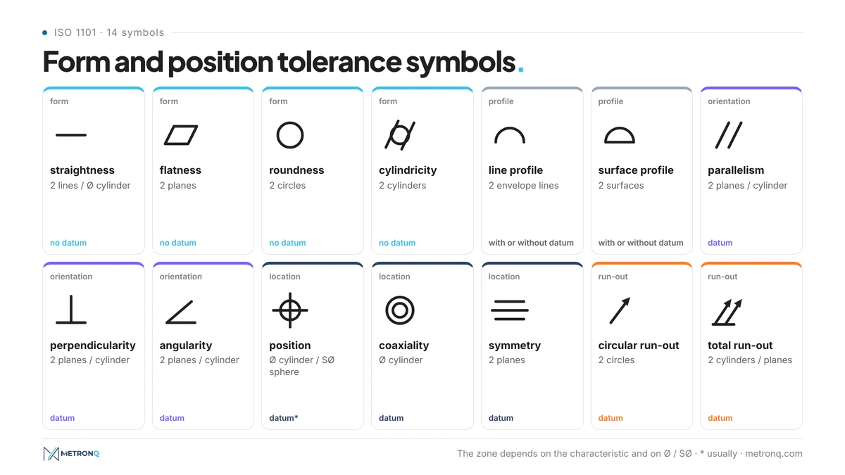
The geometric tolerance symbols are the 14 characters of ISO 1101 that a technical drawing places in the first compartment of the feature control frame. The value follows in the next compartment, then the datum letters. Form symbols have no datum, while orientation, location and run-out symbols usually have at least one.
| Group | Characteristic and symbol | Tolerance zone | Datum |
|---|---|---|---|
| form | straightness (line) | two lines or Ø cylinder | no |
| form | flatness (parallelogram) | two parallel planes | no |
| form | roundness (circle) | two concentric circles | no |
| form | cylindricity (circle between lines) | two coaxial cylinders | no |
| form or location | line profile (arc) | two envelope lines | depends on callout |
| form or location | surface profile (arc with base) | two envelope surfaces | depends on callout |
| orientation | parallelism (two strokes) | planes or cylinder | yes |
| orientation | perpendicularity (inverted T) | planes or cylinder | yes |
| orientation | angularity (angle) | planes or cylinder | yes |
| location | position (circle with cross) | cylinder, planes, sphere | usually |
| location | coaxiality (two circles) | Ø cylinder | yes |
| location | symmetry (three bars) | two planes | yes |
| run-out | circular run-out (arrow) | two circles in a section | yes |
| run-out | total run-out (two arrows) | two cylinders | yes |
The form symbols in older national standards were the same as today; mostly the names differed. The symbols described below are always read together with the value and the datums.
The circle symbol: roundness, material condition and all around
A circle on a drawing can mean three different things, so look at where it stands. A circle in the first compartment of the frame is roundness. A letter M or L in a circle after the value is the maximum or least material requirement. A small circle at the bend of the leader line means the requirement applies to the whole outline all around.
A circle with a cross is position and two concentric circles are coaxiality, so the circle symbol must always be read as a whole. An E in a circle next to a dimension is the envelope requirement of ISO 14405-1, and a P in a circle is a projected tolerance zone.
Form tolerances
Form tolerances compare the actual form of a feature with its ideal form, without any datum, and apply to single features. They include straightness, flatness, roundness and cylindricity, plus line profile and surface profile when given without datums. The form tolerance standards, above all ISO 1101, define the zone and how it is evaluated.
The standards also define how the result is obtained: by default with the minimum zone method, the narrowest zone that contains all points. They do not suggest values. The designer chooses them to suit the function, and features without a frame are covered by general tolerances, described in our article on ISO 2768 general tolerances.
Straightness deviation
Straightness deviation is the largest departure of an actual line from a straight line. For a shaft generatrix the zone is two parallel lines a tolerance value apart; for an axis with the Ø sign it is a cylinder of that diameter. Straightness is usually checked in several sections or along several generatrices.
The straightness of the actual feature is assessed from the deviations of the actual line, i.e. the points measured along the generatrix. They are measured with a straightedge, an indicator on a guide or a coordinate measuring machine. For long parts, such as a 500 mm shaft, the result depends strongly on support during measurement, because the shaft sags under its own weight.
Flatness deviation
Flatness deviation is the smallest distance between two parallel planes that contain the whole surface. The flatness of an actual feature does not depend on its orientation: the surface may be tilted relative to a datum and still meet the requirement. Orientation is only limited by a parallelism or perpendicularity tolerance.
Flatness is measured on a surface plate with an indicator, with an optical flat or on a coordinate measuring machine. Methods, their accuracy and a worked example are in our separate article on flatness tolerance.
Roundness deviation and cylindricity
Roundness deviation is the difference in radius between two concentric circles that contain the actual profile in a given section. Roundness is assessed in sections perpendicular to the axis, on the surface rather than on the axis; typical causes are lobing from three-jaw chuck clamping and from centreless grinding.
Cylindricity extends roundness to the whole cylindrical surface: the zone is two coaxial cylinders. A cylindrical surface with a cylindricity tolerance therefore has limited roundness, straightness of generatrices and taper at the same time. Roundness measured in several sections does not replace cylindricity, because it does not detect taper or bending.
Roundness is measured on a roundness tester or a coordinate measuring machine. Measuring with an indicator in a V-block gives a result that depends on the V angle and the number of lobes, so it suits shop-floor checks but not dispute resolution.
Line profile deviation
Line profile deviation was called "deviation of a specified contour" in older Polish standards. The zone is the band between two lines enveloping circles whose diameter equals the tolerance value and whose centres lie on the ideal contour defined by theoretically exact dimensions. It is assessed in each section separately.
Line profile is used for cams, blade edges and cut contours, where the form in a section matters rather than the whole surface. Without datums it controls only form; with datums it also controls the location of the contour. It is sometimes confused with straightness, but it applies to any contour, not just a straight line.
Surface profile deviation
Surface profile deviation was called "deviation of a specified surface" in older Polish standards. The zone is the space between two surfaces enveloping spheres whose diameter equals the value in the frame and whose centres lie on the ideal surface of the model. Every point of the actual surface must lie in this space, and a single point outside it makes the part nonconforming.
The surface profile tolerance is the most versatile callout: it covers planes, cylinders and freeform surfaces, i.e. any geometric shape defined in the model. It often replaces several separate frames on castings and forgings. Without datums it controls only form; with datums it also controls location. Deviations from the model are measured on a coordinate measuring machine, and the report lists each one point by point, with plus outside the material.
Orientation tolerance: parallelism, perpendicularity and angularity
An orientation tolerance limits the tilt of a feature relative to a datum, but not its distance from it. It covers parallelism, perpendicularity and angularity. Every orientation tolerance also covers form: the parallelism zone of 0.05 is two planes, so the flatness of that surface is automatically limited to 0.05.
That is why a separate form frame is given only when it must be tighter. The datum is a datum plane or datum axis established from the datum feature, marked on the drawing with a triangle and a letter. The datum feature is the real surface from which the datum is derived.
Parallelism deviation
Parallelism deviation is the distance between two planes parallel to the datum that contain the actual surface. For a hole axis with the Ø sign the zone is a cylinder parallel to the datum. Parallelism deviation also limits the flatness of that surface.
The parallelism of two planes is measured with an indicator on a surface plate: the part rests on its datum on the plate and the indicator travels over the toleranced surface. The difference between the extreme readings is the parallelism deviation, because the plate represents the datum plane.
Perpendicularity deviation
Perpendicularity deviation is the width of a zone set at 90° to the datum that contains the actual feature. For a plane the zone is two parallel planes perpendicular to the datum, for a hole axis a cylinder perpendicular to the datum. It is measured with a square, an indicator against a square or a coordinate measuring machine.
Angularity deviation
Angularity works like perpendicularity, but for any angle. The nominal angle is given as a theoretically exact dimension in a rectangular frame, and the zone is two planes inclined to the datum at that angle. An angular dimension tolerance in degrees gives a wedge-shaped zone, while an angularity tolerance gives a zone of constant width.
Location tolerances
This group limits where a feature sits relative to datums. It includes position, coaxiality and symmetry, and in older Polish standards also intersection of axes. Each of them also limits the orientation and form of the same feature, unless the drawing gives tighter values for those.
The ideal location is defined by theoretically exact dimensions from the datums, shown in rectangular frames without tolerances. The whole allowance for location error sits in the feature control frame, not in the dimensions. This gives a round zone rather than the square one produced by ± coordinate tolerancing.
Position deviation
Position deviation is the distance of the actual location of a feature from its ideal location. A position tolerance of Ø 0.1 on a hole axis gives a cylinder 0.1 mm in diameter, so the maximum permissible deviation of the axis is 0.05 mm in any direction. Position is the most widely used tolerance in this group.
On a coordinate measuring machine the location of the measured feature is calculated from the axis coordinates relative to the datums. The position deviation follows from the offsets in both axes:
where:
- - position deviation as a diameter [mm],
- - offset of the axis in X from the ideal location [mm],
- - offset of the axis in Y from the ideal location [mm].
Example (example values): the hole axis is offset by 0.024 mm in X and 0.032 mm in Y. The radial offset is 0.040 mm and the position deviation as a diameter is 0.080 mm. With a position tolerance of Ø 0.1 the hole is good. The same axis with ±0.03 on each coordinate would fail in Y, even though it lies within the round zone.
The permissible deviation is the radius of the zone, i.e. half the tolerance value. The maximum permissible deviation grows when the frame contains an M in a circle, as described below.
Coaxiality deviation
Coaxiality deviation is the diameter of the smallest cylinder coaxial with the datum axis that contains the actual axis. A coaxiality tolerance of Ø 0.02 means the journal axis may deviate from the datum axis by at most 0.01 mm. It requires a datum, usually the axis of another journal or bore.
Coaxiality is hard to measure without a coordinate measuring machine, because the axis has to be established, not the surface. On the shop floor it is often replaced by a run-out check. For a perfectly round journal the radial run-out reading equals twice the axis offset, i.e. the coaxiality value as a diameter.
Coaxiality is sometimes specified where run-out, which is easier to measure, would be enough. It makes sense for bearing axes and pin bores, where the axis itself matters. The same symbol means concentricity when the tolerance applies to a centre point in a single section rather than an axis.
Symmetry deviation
Symmetry deviation is the width of the zone between two planes placed symmetrically about the datum plane that contains the median plane of the feature. It is used for keyways, splines and jaws. Symmetry 0.04 allows the median plane of a slot to move 0.02 mm to each side.
The symmetry of a slot is measured by measuring the distance of both walls from the datum and taking half the difference. The result depends on how the datum plane was established, so the datum feature must be unambiguous on the drawing.
Intersection of axes deviation
Intersection of axes deviation is the distance between two axes that should intersect according to the drawing, for example the bore axes in a bevel gearbox housing. Older Polish standards had a separate tolerance for it. ISO 1101 has no separate symbol, and the requirement is usually expressed as a position tolerance of one axis relative to the other as a datum.
Run-out tolerance
This group limits the indicator reading while the part rotates about the datum axis through a full revolution. Run-out combines form and location in one measurement: the result includes roundness and axis offset. Circular run-out applies to individual sections, total run-out to the whole surface.
The run-out tolerance zone is always referred to the datum axis, usually established from the bearing journals. It does not say where the error comes from, only how large the combined effect is, which is why run-out describes the function of rotating parts well.
Radial run-out deviation
Radial run-out deviation is the difference between the highest and lowest readings of an indicator set perpendicular to the axis during a full revolution of the part about the datum axis. The zone is two concentric circles in each section, centred on the datum axis. Circular run-out applies in each section separately.
The part is held between centres or in V-blocks under the datum journals. Radial run-out measured in several sections can give different values, and the largest of them counts.
Total radial run-out deviation
Total radial run-out deviation is the combined indicator reading while the indicator travels along the whole cylindrical surface during rotation, without resetting. The zone is two coaxial cylinders whose axis coincides with the datum axis. Total run-out covers the cylindricity and coaxiality of that surface.
Total run-out is therefore more demanding than circular run-out of the same value. A cylindrical surface may meet circular run-out in every section and fail total run-out if it is slightly tapered.
Maximum material requirement and the axis interpretation
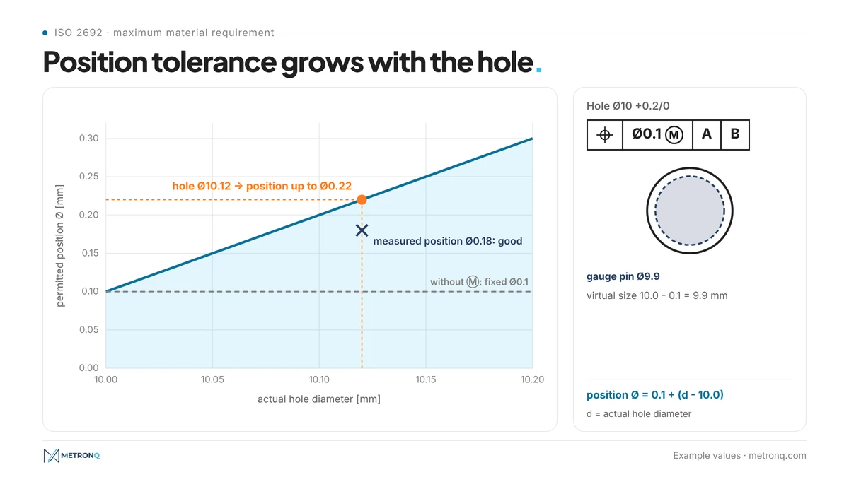
The maximum material requirement, marked with an M in a circle according to ISO 2692, allows a larger location or orientation deviation when the size of the feature departs from maximum material. For a hole, maximum material is the smallest diameter; for a shaft, the largest. It is used where assembly matters, for example for bolt holes.
Example (example values): a hole Ø10 +0.2/0 with a position tolerance of Ø 0.1 and the maximum material requirement. At a diameter of 10.00 mm the position may deviate by Ø 0.1. At an actual diameter of 10.12 mm a position of Ø 0.22 is permitted, because 0.12 mm is added to the tolerance. The virtual size is 10.0 - 0.1 = 9.9 mm, and a gauge pin of that size must enter the hole.
The least material requirement, an L in a circle, works the other way round and ensures a minimum wall thickness. Its additional tolerance grows as the feature approaches maximum material. In both cases the tolerance depends on the actual size, so parts from the same batch have different permissible deviations.
Axis interpretation and surface interpretation
The axis interpretation and the surface interpretation are two ways of reading a position tolerance on a feature of size. The axis interpretation says the hole axis must lie within the cylindrical tolerance zone. The surface interpretation says the hole surface must not violate the virtual boundary, a cylinder of the virtual size.
For a straight hole both give the same result. The axis interpretation corresponds to what a coordinate measuring machine calculates, the surface interpretation to what a functional gauge checks, i.e. a pin of the virtual size. For a bent or tapered hole the results can differ.
According to ASME Y14.5, the surface interpretation takes precedence when they differ. The axis interpretation could then accept a hole a bolt will not enter. ISO 2692 defines the maximum material requirement through the virtual boundary, so in practice the surface interpretation applies there too.
The report should state which method was used: the axis interpretation gives the CMM result, the surface interpretation the gauge result. For functional checks with an M modifier, the axis interpretation is a simplification, while the surface interpretation reflects how the part works in assembly.
Form and position tolerances on technical drawings
On a technical drawing, form and position tolerances always refer to datums and to theoretically exact dimensions. The drawing must clearly show the datum feature, the order of datums in the frame and whether the value carries the Ø sign. Without that, the same frame can mean two different things.
The order of datums in the frame matters. The primary datum (A) is usually a large plane on which the part rests, the secondary datum (B) aligns it along an edge, and the tertiary datum (C) locks the last translation. The datum feature should be stable and accessible for measurement, and on castings it is replaced by datum targets.
How to read position and form tolerances in the frame
The frame is read from left to right: symbol, value with any Ø, modifiers, datums in order of precedence. The frame "position | Ø 0.1 M in a circle | A | B | C" means: the hole axis lies within a Ø 0.1 cylinder at maximum material, located by theoretically exact dimensions from datums A, B and C.
The form of the datum features matters too. If datum A is convex, the part rocks, and every tolerance measured from it depends on a random setup. That is why datum planes often get their own flatness frame, and the surface the measurement rests on should be machined before the others are measured.
Geometry and the number of frames also affect cost. Parts rarely need a tolerance on every surface, and frames are worth giving only where function matters. Every tight frame means another measurement, sometimes another setup or grinding. In MetronQ's shop panel the price of a part is broken down by operation, so the process engineer sees what the operation driven by a tight tolerance costs. We cover the link between tolerances and price in the article on tolerances and CNC machining cost.
Frequently asked questions about form and position tolerances
What is geometric dimensioning and tolerancing?
It is a drawing notation system, known by the abbreviation GD&T, in which feature control frames for form, orientation, location and run-out are given in addition to dimensions. In Europe it is defined by ISO 1101 and related standards, in the USA by ASME Y14.5. The two systems are similar but differ in details.
What is a form tolerance and how are form tolerances specified?
Form tolerance is the group covering straightness, flatness, roundness, cylindricity, and line and surface profile without datums. Form tolerances are specified in a frame with two compartments, symbol and value, without datum letters. The value is the full width of the zone, not a deviation to one side.
When should parallelism be used instead of flatness?
Parallelism is used when a surface must not only be flat but also oriented relative to a datum, for example two mating faces of a housing. Parallelism automatically limits flatness to the same value. Flatness is given separately only when it must be tighter than parallelism, or when the surface has no datum.
How are form and position tolerances read on a drawing?
The frame is read from left to right: characteristic symbol, value with any Ø sign, modifiers such as M in a circle, and datum letters in order of precedence. Datums are found on the drawing by triangles with letters, and the ideal location by dimensions in rectangular frames. No datum letters means a form tolerance.
Does a size tolerance also limit the form of a part?
No, a size tolerance limits only size, for example a diameter measured between two points, while form, orientation, location and run-out are limited by geometric frames. Under the independency principle of ISO 8015 both apply separately, unless the drawing uses the envelope requirement or the maximum material requirement, which link them.
Sources
- 1.ISO 1101:2017, Geometrical product specifications (GPS) - Geometrical tolerancing - Tolerances of form, orientation, location and run-out
- 2.ISO 2692:2021, Geometrical product specifications (GPS) - Geometrical tolerancing - Maximum material requirement (MMR), least material requirement (LMR) and reciprocity requirement (RPR)
- 3.ISO 8015:2011, Geometrical product specifications (GPS) - Fundamentals - Concepts, principles and rules
- 4.ISO 5459:2011, Geometrical product specifications (GPS) - Geometrical tolerancing - Datums and datum systems
- 5.ISO 14405-1:2016, Geometrical product specifications (GPS) - Dimensional tolerancing - Part 1: Linear sizes
- 6.ASME Y14.5-2018, Dimensioning and Tolerancing
Read next
Automatic CNC machining quotes
Priced from the 3D model or the drawing, on your machines and your rates. You just approve it. 8 free quotes to start and 1 every month, no card.
Create a free account