ISO 2768 General Tolerances: Classes and Tables
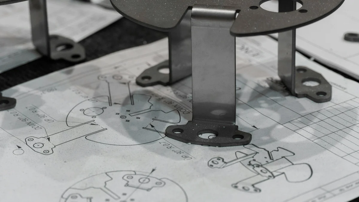
Dimensions for which the drawing gives no deviations get their tolerances from the ISO 2768 tables. A single class entry in the title block, e.g. mK, gives every dimension without its own tolerance clear limits. Below you will find the tables for classes f, m, c and v, the form and position tolerances of classes H, K and L, an example of reading a drawing and practical rules for choosing a class.
ISO 2768: what it is and when it applies
ISO 2768 is the standard for general tolerances of parts made by machining and from sheet metal. Its first part (1989) gives tolerances for linear and angular dimensions in four classes, and the second part gave form and position tolerances in classes H, K and L. It applies when the drawing calls it up.
Without such an entry, a dimension without deviations formally has no tolerance at all, and a dispute over whether the part is good is settled only by the contract with the customer. That is why a recognised tolerance standard in the title block is the first thing a process engineer checks on a new drawing. It also simplifies the drawing: the designer writes deviations only where function requires them.
Status in 2026: part 1 from 1989 is still current (last confirmed in 2022), and a new single-part edition of ISO 2768 is being published. Part 2 was withdrawn in 2021 and replaced by ISO 22081, which does not provide a ready table of values. On existing drawings, however, the H, K, L classes are still very common.
Why title block tolerances matter
General tolerances mean that every dimension has limits, even when no symbol stands next to the number. The designer writes deviations only on dimensions that matter for function and covers the rest with one entry. The drawing is easier to read, and the process engineer immediately sees which dimensions are critical and which are free.
Dimensional accuracy plays a key role in assembly and in how a part works, but not every number on a drawing is equally important. Tolerances for untoleranced dimensions ensure that a free dimension, such as the length of a flange or the width of a chamfer, does not stray from nominal further than typical machining in that class allows. Well-chosen tolerances ensure the part works without paying for accuracy nobody needs, and they keep assembly repeatable in series production.
The class in the title block also acts as an agreement between designer and manufacturer: every clearly specified tolerance, whether a standard, a symbol or deviations, is binding and says what shop accuracy the drawing assumes. Class f means more accurate machining, while class c allows faster and cheaper production methods.
Types of tolerance: dimensional, geometrical and general
A drawing carries three types of tolerance. Dimensional tolerances limit size, geometrical tolerances limit form, orientation, location and run-out, and general tolerances cover all dimensions without their own tolerance in one entry. Each type is described by a different standard and checked with different instruments, and dimensional tolerances are the easiest to measure.
Dimensional tolerances are written numerically (Ø25 +0.1/0) or as an ISO 286 symbol (Ø25 H7). How to calculate deviations and limits of size is shown in our article on dimensional tolerance. Geometrical tolerances (GD&T) are written in feature control frames according to ISO 1101, the basic standard for geometrical tolerancing in the ISO system.
The tolerancing standards form a system: ISO 286 for fits, ISO 1101 for geometry, ISO 2768-1 for free dimensions and ISO 8015 for the rules that tie it all together. Under ISO 8015 the independence principle applies: size and geometry are checked separately unless the drawing requires otherwise.
Tables and ranges for classes f, m, c, v
The tables in part 1 give permissible deviations in four classes: f (fine), m (medium), c (coarse) and v (very coarse). All deviations are symmetric, i.e. plus and minus the same value. The larger the nominal size, the wider the tolerance in a given class, just as with the IT grades.
Tolerances for linear dimensions
Tolerances for linear dimensions apply to lengths, diameters, distances and thicknesses. Values in millimetres:
| Nominal size [mm] | f | m | c | v |
|---|---|---|---|---|
| 0.5 to 3 | ±0.05 | ±0.1 | ±0.2 | - |
| over 3 to 6 | ±0.05 | ±0.1 | ±0.3 | ±0.5 |
| over 6 to 30 | ±0.1 | ±0.2 | ±0.5 | ±1 |
| over 30 to 120 | ±0.15 | ±0.3 | ±0.8 | ±1.5 |
| over 120 to 400 | ±0.2 | ±0.5 | ±1.2 | ±2.5 |
| over 400 to 1000 | ±0.3 | ±0.8 | ±2 | ±4 |
| over 1000 to 2000 | ±0.5 | ±1.2 | ±3 | ±6 |
| over 2000 to 4000 | - | ±2 | ±4 | ±8 |
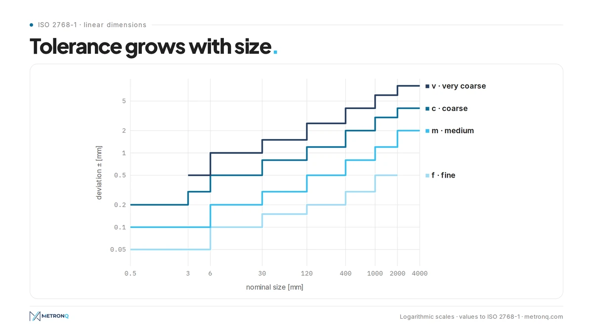
For dimensions below 0.5 mm the standard gives no values, so deviations must be written next to the dimension. The same tolerance calculator that calculates fit classes also gives the value from this table for any dimension.
External radii and chamfer heights
| Nominal size [mm] | f and m | c and v |
|---|---|---|
| 0.5 to 3 | ±0.2 | ±0.4 |
| over 3 to 6 | ±0.5 | ±1 |
| over 6 | ±1 | ±2 |
Tolerances for angular dimensions
Tolerances for angular dimensions depend on the length of the shorter leg of the angle, not on the angle itself. The longer the leg, the smaller the permitted angular deviation, because the same angle error produces a larger offset on a long leg. Angular tolerances are given in degrees and minutes.
| Shorter leg [mm] | f and m | c | v |
|---|---|---|---|
| up to 10 | ±1° | ±1°30' | ±3° |
| over 10 to 50 | ±0°30' | ±1° | ±2° |
| over 50 to 120 | ±0°20' | ±0°30' | ±1° |
| over 120 to 400 | ±0°10' | ±0°15' | ±0°30' |
| over 400 | ±0°5' | ±0°10' | ±0°20' |
The angular tolerances in the table apply to the general direction of lines or surfaces, not to their form. In practice the most common case is a 45° chamfer: a chamfer with a 2 mm leg in class m may have an angle from 44° to 46°.
General geometrical tolerances: classes H, K and L
The geometrical tolerances of the former part 2 limit flatness, straightness, perpendicularity, symmetry and run-out of features without a feature control frame. Class H is the finest, K medium and L coarse. They are written together with the dimensional class, e.g. mK, meaning class m for dimensions and K for geometry.
| Characteristic | Range [mm] | H | K | L |
|---|---|---|---|---|
| flatness and straightness | up to 10 | 0.02 | 0.05 | 0.1 |
| flatness and straightness | over 10 to 30 | 0.05 | 0.1 | 0.2 |
| flatness and straightness | over 30 to 100 | 0.1 | 0.2 | 0.4 |
| flatness and straightness | over 100 to 300 | 0.2 | 0.4 | 0.8 |
| flatness and straightness | over 300 to 1000 | 0.3 | 0.6 | 1.2 |
| perpendicularity (shorter leg) | up to 100 | 0.2 | 0.4 | 0.6 |
| perpendicularity (shorter leg) | over 100 to 300 | 0.3 | 0.6 | 1 |
| symmetry | up to 100 | 0.5 | 0.6 | 0.6 |
| radial and axial run-out | any | 0.1 | 0.2 | 0.5 |
Roundness equals the diameter tolerance, but not more than the run-out from the table. Parallelism equals the larger of the size tolerance or the flatness. These values come from a standard withdrawn in 2021, so new drawings increasingly use ISO 22081, where the designer specifies the values. The suffix E, e.g. mK-E, applies the envelope requirement to all single features of size.
ISO 1101 remains the basis: any feature control frame on the drawing overrides the title block entry. The general geometrical tolerances from the table apply only to features without their own frame.
Example of specifying tolerances on a drawing
A tolerance specification is best shown on a simple part. A steel plate 120 × 80 × 20 mm has a Ø20 hole without deviations, a 1 × 45° chamfer and a 30° bevel on a 25 mm leg, and the title block contains class mK. Each of these dimensions gets its limits from the class m and K tables.
| Dimension on drawing | Table range | Tolerance in class m/K | Limits |
|---|---|---|---|
| length 120 | over 30 to 120 | ±0.3 | 119.7-120.3 |
| width 80 | over 30 to 120 | ±0.3 | 79.7-80.3 |
| thickness 20 | over 6 to 30 | ±0.2 | 19.8-20.2 |
| hole Ø20 | over 6 to 30 | ±0.2 | 19.8-20.2 |
| chamfer 1 × 45° | 0.5 to 3 | ±0.2 and ±1° | 0.8-1.2 |
| bevel 30° | leg 10 to 50 | ±0°30' | 29°30'-30°30' |
| flatness of the large face | over 100 to 300 | 0.4 | - |
| perpendicularity of sides | up to 100 | 0.4 | - |
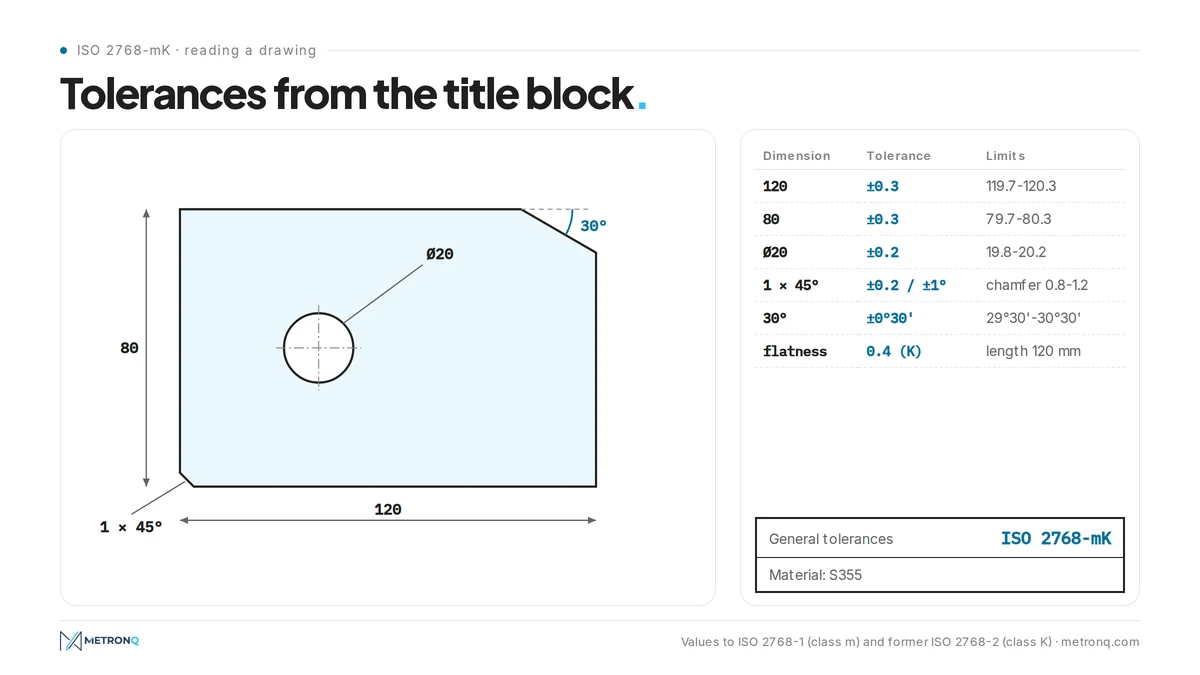
A typical example for class m: a 50 mm dimension is ±0.3 mm and a 10 mm dimension ±0.2 mm. A shop-floor example: if the Ø20 hole is a clearance hole for an M18 bolt, class m is enough, but if a bush is to run in it, the designer must specify an ISO 286 class, e.g. Ø20 H7. The opposite case: the 120 dimension on the outer contour of the plate affects nothing and needs no deviations.
ISO 2768 vs ISO 286: which system when
ISO 286 describes fit tolerances, i.e. holes and shafts that work together, while the title block covers everything else. Both standards describe dimensional tolerances, but in different scopes. A dimension with a symbol such as H7 or g6 always takes precedence over the title block. Any dimension that must ensure a proper fit gets its own symbol.
The difference is large: Ø25 in class m is ±0.2 mm, a zone of 400 µm, while Ø25 H7 is a 21 µm zone. Precision fits therefore always need their own symbol, and bearing fits also the manufacturer's catalogue, because the title block cannot ensure a proper bearing or bush fit. Tolerances for bearings and for drive shafts at bearing seats, seals and gears are always specified from fit tables and the bearing catalogue.
In practice, both systems appear on one shaft: bearing journals in k5 or k6, while step lengths, chamfers and undercuts stay in class m. The shaft diameter outside fit locations, e.g. on a free section between journals, can safely remain in the title block class. IT grades and their values are covered in our article on IT tolerance grades, and the selection of hole-shaft pairs in our fit tolerance chart.
Tolerances in production processes
The accuracy that can be held depends on how the part is made. The same class m means something different for milling, sheet metal bending and flame cutting, because every production process has a different natural accuracy. That is why the class in the title block is chosen for the manufacturing method, not just for the function of the part.
CNC machining holds class m without difficulty, and with stable clamping also class f. Laser cutting and sheet metal bending usually fall within class m or c, depending on thickness and the number of bends. Gas and plasma cutting of thick plate is usually class c or v. Process tolerances, i.e. the accuracy a process achieves in series production, should be smaller than the drawing tolerance, otherwise scrap appears.
Tolerances for production processes are worth knowing before quoting, and process capability worth checking on the first parts of a batch, because they decide the number of operations. Class f on a large plate may require an extra finishing pass, while class c allows it to be skipped entirely. A class poorly matched to the method ends with the part needing machining nobody included in the quote.
Scope of the standard: materials and industries
The standard covers machined parts and parts formed from sheet metal, regardless of material. Tolerances for steel and for aluminium in class m are therefore the same: ±0.3 mm for 50 mm. Other processes, such as casting, forging, welding and plastic moulding, have their own standards that must be called up separately.
Material behaviour matters more than the standard here, which is why tolerances are set with temperature, moisture and elasticity in mind. Aluminium expands almost twice as much as steel, so tolerances for steel/aluminium in class f should be measured at the 20°C reference temperature, and steel and aluminium parts should be measured at the same temperature. In mixed assemblies of steel/aluminium, the tolerances are chosen with a margin for the difference in expansion. Machined plastics are also covered by this standard, but plastics creep and absorb moisture, and tolerances for injection-moulded plastics are defined separately by ISO 20457. Tolerances for composite materials are usually set individually, because they depend on the fibre layup.
Cut and bent sheet metal falls within the standard, while tolerances for welded steel structures are given by ISO 13920 and the execution of steel structures by EN 1090-2. For sheet thicker than a few millimetres, bending tolerances should be agreed with the manufacturer. Castings have their own classes under ISO 8062-3, and tolerances in building construction, including concrete structures, are covered by standards such as DIN 18202, not by a standard for machine parts. Writing mK on such parts misleads the manufacturer.
Tolerances in aerospace and ASME Y14.5
Tolerances in aerospace rarely rely on a title block with class m. Aerospace drawings, especially in US supply chains, are made to ASME Y14.5, which has no table of general tolerances: values are given in the title block by number of decimal places or directly at the dimensions. Service tolerances of aircraft parts come from stress analysis, not from a general standard.
An important difference: ASME Y14.5 applies the envelope principle (Rule #1) by default, while ISO 8015 applies the independence principle. The same drawing with a Ø20 ±0.1 dimension therefore means something different in each system, and you always need to check which standard it was made to.
Assembly of parts and joint stability
Assembly depends on whether the tolerances of the parts that go together actually match. The title block class is enough for free dimensions, but when two parts are to be joined with bolts or dowels, the tolerance chain may cause the holes not to line up. The assembly process is therefore planned together with the tolerances.
Tolerances of machine elements assembled with bolts decide everything here, and bolted joints are a typical example. Under ISO 273 the clearance hole for an M10 bolt is 10.5 mm in the fine series, 11 mm in the medium and 12 mm in the coarse series. The tolerance of a bolted joint comes from this clearance: with an 11 mm hole and a 10 mm bolt, the position of each hole can deviate by ±0.5 mm before the bolt stops going in. Title block tolerances fit within this clearance: an 80 mm hole spacing in class m is ±0.3 mm. With a 10.5 mm hole from the fine series the margin is only ±0.25 mm and the title block is no longer enough.
Joint stability depends on the clearance not being too large: bolted joints with large clearance transmit forces by friction and may slip under dynamic load. In structures exposed to vibration, bolted joint tolerances are better specified as a position tolerance than left to the title block. Machine elements working under alternating load always need more attention than static ones.
Clearance fit too loose
A fit that is too loose means the clearance between parts is larger than function requires. The shaft knocks in the bush, the gear runs out and the joint loses stiffness. A loose fit under dynamic loads leads to rapid joint wear and noise.
Serious operating problems start with clearance. The main problems caused by too much clearance are vibration, part wear due to excessive play, and external forces shifting the position of components. This often means a costly replacement of the whole assembly, not just one part, because worn surfaces are hard to fit again. A costly part replacement in a production machine also means downtime, which generates additional costs.
Fit too tight
A fit that is too tight means parts cannot be assembled, or have to be forced together with a load the design does not allow for. A tight fit where clearance was intended causes seizure and overheated bearings, so the mechanism fails sooner than expected. This is a typical result of a poorly chosen tolerance.
Assembly problems with tolerances that are too tight mean extra machining during assembly, lapping, or replacing parts with new ones. Parts are hard to fit, assembly takes longer, and the lead time grows. A forced interference also significantly reduces durability, because assembly stresses add to the operating stresses.
Best practices for general tolerances
Best practice comes down to one rule: the title block class for free dimensions, an individual tolerance for functional dimensions. The class is chosen for the manufacturing method, and every dimension important for a fit, a seal or assembly gets deviations or a frame. This approach lowers cost and prevents disputes, because tolerancing standards take precedence over shop habits.
- Always enter the standard number together with the class in the title block, e.g. ISO 2768-m. No entry means no tolerance.
- For machining choose class m, and f only where accuracy is really needed. Class f raises the cost of all dimensions at once.
- Specify fits according to ISO 286 and function-critical geometry with a frame according to ISO 1101.
- Check the tolerance chains for holes for bolted joints and dowels.
- On new drawings consider ISO 22081 instead of the withdrawn classes H, K, L.
Tolerances that are too tight mean higher production costs: each finer class means slower machining, more frequent measurement and precise dimensional inspection on a measuring machine. Tolerances that are too loose reduce product life and, by increasing the risk of complaints, impair the functionality of the finished product. Well-chosen tolerances are the compromise in which the finished product works, the parts meet the standards and production cost does not grow without need.
This compromise shows up in production costs: how tolerances translate into time and part price is covered in tolerances vs CNC machining cost. In MetronQ, machining times are calculated for the machines the shop enters and calibrates itself, so the accuracy class on the drawing translates into real time on a specific machine: machines and calibration.
Frequently asked questions about general tolerances
What does mK mean according to ISO 2768?
The mK entry means class m for linear and angular dimensions and class K for geometry without frames. A 50 mm dimension then has a tolerance of ±0.3 mm, and the flatness of a 200 mm long face is 0.4 mm. Class K comes from part 2 of the standard, withdrawn in 2021, but is still widely used.
Does a dimension outside the title block tolerance mean scrap?
Not always. Part 1 of the standard says that exceeding such a tolerance should not automatically lead to rejection of the part if its function is not impaired. Acceptance tolerances should still be agreed with the customer before production, because in practice many quality departments reject any dimension outside tolerance.
Is the standard still valid?
Part 1 from 1989 is valid and was last confirmed in 2022, and a new edition is being published. Part 2 with geometrical classes H, K and L was withdrawn in 2021 and replaced by ISO 22081. Older drawings with mK remain valid, because they call up a specific edition of the standard.
Which class should I choose for CNC machining?
For typical machining, class m is chosen most often, because CNC machines hold it without additional operations. Class f is used on small precision parts, and class c on sheet metal structures and large parts. Fit dimensions are specified separately with fit symbols anyway.
How do title block tolerances differ from ISO 286?
ISO 286 gives tolerances for dimensions that work in fits, in micrometres and with a zone position that depends on the letter. Title block values are symmetric, much wider, and cover dimensions without their own indication. Both systems are used on one part at the same time: fits with symbols, everything else from the title block.
Sources
- 1.ISO 2768-1:1989, General tolerances - Part 1: Tolerances for linear and angular dimensions without individual tolerance indications
- 2.ISO 2768-2:1989, General tolerances - Part 2: Geometrical tolerances for features without individual tolerance indications (withdrawn 2021)
- 3.ISO 22081:2021, Geometrical product specifications (GPS) - Geometrical tolerancing - General geometrical specifications and general size specifications
- 4.ISO 1101:2017, Geometrical tolerancing - Tolerances of form, orientation, location and run-out
- 5.ISO 8015:2011, Fundamentals - Concepts, principles and rules
- 6.ISO 286-1:2010, ISO code system for tolerances on linear sizes
- 7.ISO 273:1979, Fasteners - Clearance holes for bolts and screws
- 8.ISO 13920:1996, Welding - General tolerances for welded constructions
- 9.ISO 8062-3:2007, Dimensional and geometrical tolerances for moulded parts
- 10.ISO 20457:2018, Plastics moulded parts - Tolerances and acceptance conditions
- 11.ASME Y14.5-2018, Dimensioning and Tolerancing
- 12.Tabellenbuch Metall, Europa-Lehrmittel (general tolerances)
Read next
Automatic CNC machining quotes
Priced from the 3D model or the drawing, on your machines and your rates. You just approve it. 14 days free, no card.
Create a free account