Feed Rate: Per Rev, Per Tooth and Per Minute
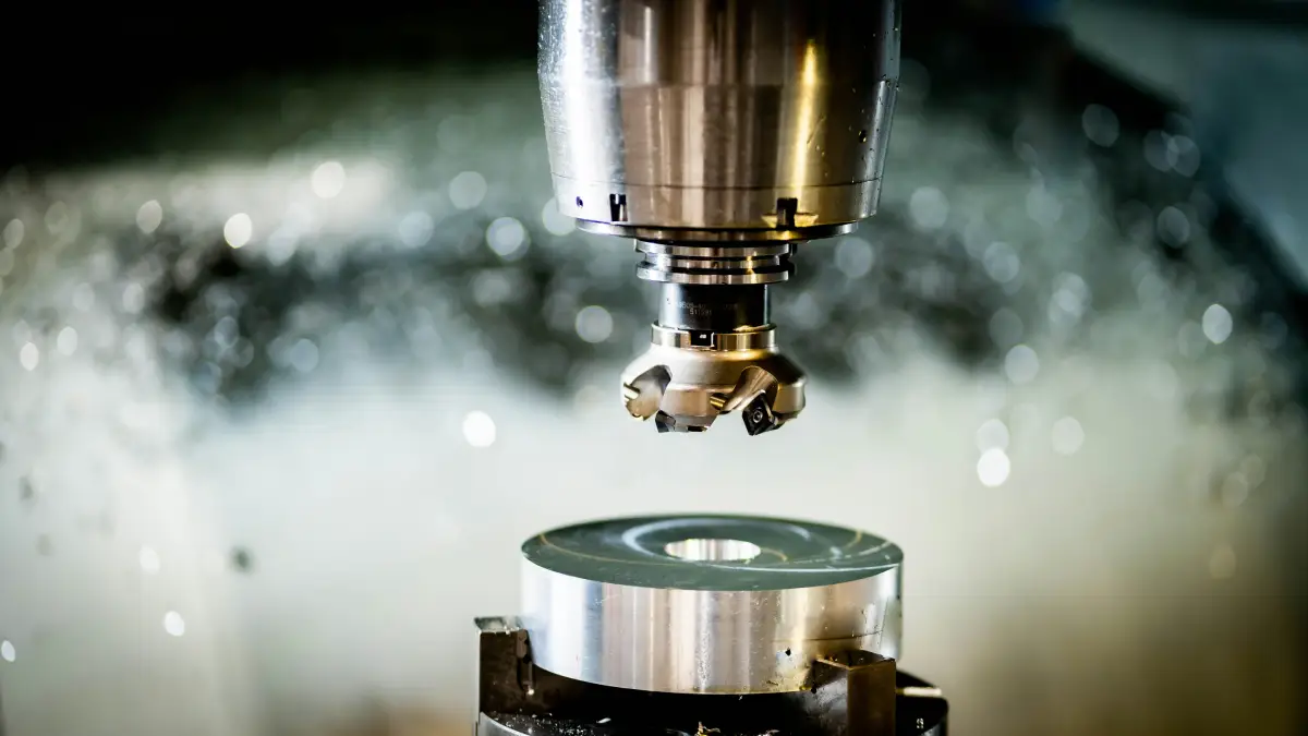
One parameter, three different numbers: 0.2 mm/rev on a lathe, 0.08 mm per tooth on a cutter and 900 mm/min in the F address of a program. All three are called "feed" - and that is exactly why feed rate is the most commonly confused machining parameter. This guide sorts out the definitions of , and table feed, shows how to convert between them, explains what feed does to chip thickness, forces and surface finish - and why too little feed ruins cutting edges just as effectively as too much.
What feed means in machining
In machining, feed describes how quickly the tool advances into successive layers of material - as opposed to cutting speed, which describes how fast the edge travels ACROSS the material. That distinction is the heart of the whole cutting process: speed governs temperature and edge wear, feed governs chip thickness, forces and what is left on the surface.
Choosing the right cutting speed is covered in our separate guide on cutting speed; here the spotlight belongs entirely to feed.
Formally, feed is the distance the tool travels relative to the workpiece per reference unit - and it is precisely the choice of that unit that produces the three quantities you meet in practice. The first relates the distance to one spindle revolution. Feed per tooth relates it to a single cutting edge. Feed per minute (table feed) relates it to one minute of work. Physically they describe the same phenomenon; they differ in what they are pinned to, which makes each convenient in a different place: on the lathe, when selecting edge load, in the NC program and when estimating cycle time.
Why does this matter so much? Because mixing up these three quantities is the shortest road to a snapped end mill or to an hour-long cycle that should take fifteen minutes. The cutting process forgives a lot, but not a table feed typed where the control expected a feed per revolution.
Three feeds: fn, fz and table feed
Feed comes in three forms that differ only in their reference unit: is the distance per spindle revolution (mm/rev), is the distance per cutting edge (mm), and is the distance per minute (mm/min). Spindle speed and the number of working teeth link them, so any one of them converts into the other two.
Let us start with the formal definitions and units - they cause all the confusion:
| Quantity | Symbol | Definition | Where it is used |
|---|---|---|---|
| Feed per revolution, (mm/rev) | distance per 1 spindle revolution | turning, drilling | |
| Feed per tooth, (mm) | distance per 1 cutting edge | milling - edge load selection | |
| Feed per minute / table feed, (mm/min) | distance per minute | NC programs, machining time |
The conversions are simple and worth memorising. Table feed is , where is the spindle speed and the number of teeth (more precisely: the effective number - more on that below). and are linked by . Going the other way: . Whoever memorises this triangle can convert any catalogue to any control.
Practical trap no. 1: milling catalogues quote feed per tooth, while the program takes table feed - between them stand the spindle speed and the tooth count. The same 12 mm cutter at with 2 flutes and 4,000 rpm gives , and with 4 flutes - 1,280 mm/min. Trap no. 2: in turning there is no at all, so the feed per revolution is simultaneously the feed "per edge" - which is why a turner can go a whole career without ever meeting .
The F address: what you actually type into the program
The F address in NC code is the tool feed - but its meaning depends on the active preparatory function. G94 (milling machines) interprets F as a per-minute value in mm/min; G95 (lathes) - as a per-revolution value in mm/rev. Hence the classic program-porting error: F200 on a mill is a calm 200 mm/min, while F200 after G95 would mean 200 mm per revolution - the machine will of course refuse, or snap the tool on the first working move. Selecting the tool feed therefore starts trivially: by checking which mode the program runs in.
It is also worth knowing that F describes the motion of the tool's guided point, not of its edge. On straight moves that makes no difference; in circular interpolation it becomes a topic of its own, which we return to under circular milling.
Tool rpm and cutting speed: where n comes from
The per-minute feed value does not exist without spindle speed, and the tool's rpm follows from cutting speed and diameter. Calculating the spindle speed is a single rearrangement: , where is the tool diameter in milling and drilling, and the workpiece diameter in turning.
The correct cutting speed comes from the catalogue for the material-edge pair, and selecting the cutting speed always precedes selecting the feed; formulas, worked examples and starting tables are collected in our guide on how to calculate cutting parameters.
Two things in that equation tend to produce surprises. First, on a lathe the workpiece rpm changes with every pass, because the workpiece diameter shrinks and the rotational speed has to keep up - which is why controls offer constant surface speed (G96), correcting the rpm on the fly. Second, at small diameters the actual cutting speed can end up below the programmed one, because the rpm calculation exceeds the machine's maximum - the spindle has a hard limit: a 3 mm cutter at "wants" over 21,000 rpm. The machine turns as fast as it can, the real cutting speed drops - and then has to be recalculated from the real rpm, not the catalogue one. This is the most common case where a cutting-speed correction drags a feed correction along with it.
The third surprise is units. Cutting speed in m/min and feed in mm/min differ by a factor of a thousand - and whoever enters the cutting speed in mm/min instead of m/min gets spindle speeds a thousand times too low. It sounds absurd, but every process engineer has seen a program after that mistake: the tool rubs, no chip comes off, the machined surface shines from work hardening. A "cutting speed in mm/min" entry in documentation is always a typo - the correct unit is m/min and only that goes into the formula. The same reflex helps when importing from CAM: if the sheet shows cutting speed in mm/min, it is the column that needs fixing, not the machine.
Selecting cutting parameters in turning
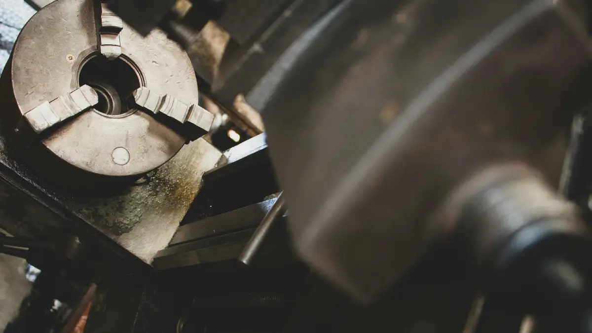
In turning, the feed plays first violin, because it directly shapes the surface. Recommended machining parameters for turning carbon steel with a 0.8 mm nose-radius insert are roughly: roughing at 2-5 mm depth of cut, finishing at 0.3-1 mm depth.
Cutting parameter values are always read in pairs: feed with nose radius, depth with edge length.
Turning parameters: fn, ap and machining time
Turning parameters are tied together by one of the most practical relationships in the trade: machining time in turning is , where is the tool path length. Doubling the feed halves the time - no other change buys time so cheaply, as long as quality allows it. Depth of cut, measured in mm per side, in turn decides the number of passes - in catalogues it is (mm). A 6 mm allowance can be removed in two passes of 3 mm or four passes of 1.5 mm, and the machining time differs by a factor of two.
The limits are set by three phenomena. From above, feed is capped by insert strength and surface roughness; depth of cut, mm by mm, stacks up forces towards the limits of power and rigidity. From below it gets more interesting: too little feed makes the edge stop cutting and start ploughing. A practical catalogue rule: the turning feed should not be less than half the edge hone radius, and on finishing passes should exceed 0.05 mm/rev. Insert geometry sets conditions too - it is the insert geometry, not the process engineer's wish, that defines the feed window: the chipbreaker has its own window of feeds and depths outside which the chip stops breaking - a ribbon wrapped around the part is almost always a sign that fell below the chipbreaker's window. We cover turning kinematics and tooling in more depth in the guide on longitudinal turning.
Table feed in milling: tooth count and chip thickness
In milling, everything revolves around the feed per tooth - it says how much material a single tooth takes in one engagement. Feed per tooth is selected from the catalogue for the cutter diameter and material: for a 10 mm solid-carbide end mill in steel, typical is 0.04-0.1 mm; in aluminium 0.08-0.15 mm.
It is then converted to the per-minute value through rpm and tooth count - and here a nuance appears that spoils calculations more often than you would expect.
z, zc and the effective number of teeth
A cutter has teeth nominally, but not all of them have to work at once. The effective number of teeth can be lower than the nominal one: a face mill gashed on every other tooth, a chamfer mill where only part of the cone engages, or indexable inserts set at different heights. The table feed formula takes the effective number, not the nominal one: . Whoever runs that conversion with the full tooth count while only half the teeth actually cut gets an twice as large as intended, and with it higher forces and a worse edge. Cutter catalogues list the tooth count as a nominal value and the effective number of teeth separately - it is worth checking which one your calculator assumes.
Average and maximum chip thickness: hm and chip thinning
Feed per tooth is the path of the tooth - but the chip that the tooth actually cuts has a different thickness, set by the entry geometry. Feed per tooth describes the intention, chip thickness the reality. At a small radial width of cut , the tooth enters the material "tangentially" and the maximum chip thickness is clearly smaller than ; a lead angle below 90 degrees does the same, stretching the same cross-section over a longer edge. Average chip thickness (mm) - not the feed itself - decides whether the edge cuts or rubs.
Hence the technique called chip thinning: when drops below the threshold (roughly 0.02-0.04 mm for carbide), the feed per tooth must be INCREASED to restore a healthy chip thickness. A cutter working peripherally at of diameter tolerates an up to twice the catalogue value - and shortens the cycle instead of destroying the edge. It is the most underrated productivity reserve in milling: free, because it hides in the geometry. Maximum chip thickness guards the upper limit in turn: it, not , defines the edge load in full slotting, where the wrap angle is largest.
Milling techniques and feed
Milling techniques differ precisely in what they do to chip thickness and feed. Linear milling (straight passes) keeps conditions constant and is the reference for catalogue . Edge milling with the cutter's periphery works at small - edge milling is the classic candidate for a chip-thinning correction.
Point milling with a ball-nose cutter at shallow depth has an effective diameter far below the nominal one: the real cutting speed at the contact point drops - the effective cutting speed there is a fraction of the nominal - so the rpm must be raised, and with it. Finally circular milling - motion along a circle - deserves its own subsection, because here the feed demands an explicit correction.
Circular milling: feed correction on arcs
In circular interpolation the cutter's centre and its edge travel on circles of different radii - and the control drives the tool centre at the programmed F. Circular milling of a pocket (internal arc) means the edge on the periphery travels FASTER than the centre: the effective feed speed (mm/min) at the edge rises - a different feed speed from the one programmed in F - by the ratio , where is the machined hole diameter and the tool diameter. Circular milling of a boss (external arc) works the other way round: the edge slows down. In practice: a 10 mm cutter circular-milling a 12 mm hole has its edge racing six times faster than its centre - without reducing F, each tooth takes six times the feed per tooth and breaks. That is why in interpolation you control the feed per tooth at the edge, not at the tool axis.
The rule: on internal arcs reduce F by the factor ; on external arcs you may raise it. Modern CAM systems do this automatically, but circular milling programmed by hand - typically thread or hole interpolation - needs the correction stated explicitly. This is also why circular milling of small holes with a large cutter is a bad idea regardless of feed: the smaller the difference in diameters, the more violent the correction.
Feed versus surface quality, forces and tool life
Feed is the parameter that shapes the machined surface quality most strongly. In turning, the theoretical roughness height grows with the square of the feed: . Halving the feed improves the theoretical profile fourfold - no other parameter has such leverage on smoothness.
How and callouts translate to the drawing is explained in our guide on surface roughness; here let us stay practical: if the machined surface after turning fails the requirement, check the feed and nose radius first, everything else second.
With forces it is the opposite of smoothness: cutting force grows almost proportionally with feed, because the chip cross-section grows. It is estimated using the specific cutting force (N/mm2) - the notional force needed to tear off 1 mm2 of chip cross-section: steel ~2,000-2,500, aluminium ~700-900, stainless ~2,400-3,000. Cutting force is, simplified, - so it rises linearly with each of the three factors - and from it follow the torque (Nm) at the spindle and the cutting power (kW). A heavy feed with a deep cut can stall a spindle not because the "machine is weak", but because the torque exceeded the drive's characteristic at low rpm. Metal removal rate describes the fourth quantity in this family: (cm3/min), the volume of material removed per minute - and it is what the whole roughing game is about, because removal rate grows directly with feed, depth and speed. Whoever compares machines or strategies should compare exactly this, not individual parameters.
Tool life reacts to feed more gently than to speed - and that is the most important asymmetry in the whole selection process. Excessive cutting speed acts exponentially: raising by 20% can halve tool life; raising feed by 20% typically costs tool life some fifteen-odd percent while cutting the time by a full 17%. The textbook conclusion therefore reads: raise productivity first with depth, then with feed, and leave cutting speed for last. Tool wear accelerates sharply only at the extremes: too much feed chips the edge mechanically, and too little - paradoxically - also destroys edges, because rubbing and plastic deformation work-harden the surface layer that the next pass then slides over. Low cutting speed combined with too little feed is a recipe for built-up edge; high cutting speed with too much feed - for an over-tempered edge. High cutting speed also raises the demands on feed uniformity, because every hesitation leaves a mark. The healthy window sits in the middle and is wider than beginners' caution suggests: when in doubt, treat the catalogue feed as a lower bound, not an upper one.
Feed's influence on machining quality also shows indirectly: a stable, decisive feed damps vibration, because the edge stays constantly loaded - and the machined surface quality feels that first. The whole process sees it as a paradox: a chattery finish at a cautious feed - quality improves after INCREASING , against the operator's intuition. Similarly with tool wear in stainless: too gentle a feed lets the edge "iron" the material, which work-hardens, and every following tooth works in a harder skin.
Symbols and formulas: a units cheat sheet
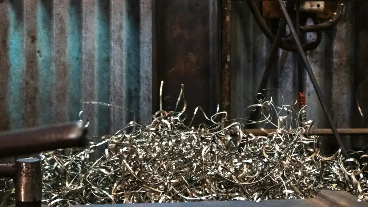
The table gathers the symbols and units used in tooling catalogues: in m/min, in rpm, in mm/rev, in mm and in mm/min, plus , , , , , and . Below it sit the core formulas that connect these quantities, from spindle speed all the way to power and torque.
Every quantity from this article in one place - in the notation used by tooling catalogues:
| Symbol and unit | Meaning |
|---|---|
| (m/min) | cutting speed, m/min |
| (rpm) | spindle speed |
| (mm/rev) | feed per revolution |
| (mm) | feed per tooth |
| (mm/min) | feed per minute (table feed) |
| (mm/min) | effective feed speed at the edge |
| , | nominal tooth count and effective number of teeth |
| (mm) | depth of cut, mm |
| (mm) | radial width of cut |
| (mm) | average chip thickness |
| (degrees) | lead (entering) angle |
| (N/mm2) | specific cutting force |
| (kW) | cutting power |
| (Nm) | torque |
| (cm3/min) | metal removal rate |
| , (mm) | tool diameter and cutting diameter, mm (of the workpiece or contact point) |
Foundation formulas: ; ; ; treat the values in this cheat sheet as a dictionary, not as settings; depends on , and ; (milling) or (turning); ; . The cutting diameter in ball-nose milling and chamfering is the diameter at the contact point, not the nominal - which is where the rpm corrections in point milling come from.
A feed calculator in practice
Every conversion from this article is done for you by our free cutting parameters calculator: you enter the material, tool and diameter, and you get the rpm, the per-minute value and the machining time with the numbers substituted into the formulas. Feed selection from Dormer Pramet, Walter and Kennametal catalogue tables is built in as starting values.
Cutting parameters and spindle speed in one tool
Modern cutting tools have their feed windows written into the chipbreaker geometry and carbide grade, which is why the calculator starts from catalogue data: turning, milling, drilling and threading, together with power, torque and tool life - and the spindle-speed check watches the machine's rpm limit, recalculating the per-minute value from the real rpm whenever the requested (m/min) is out of reach. And if you price parts more often than you calculate parameters, instant CNC quoting turns the same geometry into a full cost calculation.
Frequently asked questions about feed
What is the difference between the nominal tooth count and the effective number?
is the nominal tooth count; the effective number covers the teeth that actually cut. The per-minute formula takes the effective number; on a regular end mill both are equal, but face mills with inserts at different heights or chamfer mills engage fewer teeth, so a table feed computed with the full comes out too high.
What feed should I start with when there is no catalogue data?
A safe carbide starting point is: turning steel roughing and 0.12 finishing; milling of cutter diameter; drilling of drill diameter. It also depends on the workpiece. Then correct after the first part: chip, sound, finish. These are cautious values - treat them as a floor, not a target.
Do feeds depend on machine fixturing and workholding?
Yes, strongly: catalogue values assume a rigid setup and ideal conditions. A part on parallels in a vice, a long cutter overhang or a thin-walled sleeve in a three-jaw chuck call for a 20-40% feed reduction, because vibration destroys the edge faster than an exceeded load would. Solid fixturing is the silent precondition of every feed table.
How do I pick feeds for new machine tooling?
From the manufacturer's catalogue - for exactly that carbide grade and that geometry, not "a similar cutter". Modern cutting tools have parameter windows shifted markedly higher than their counterparts from a decade ago; running new tools on old habits wastes their potential and, curiously, often shortens tool life, because they work below a healthy chip thickness.
How does feed build an efficient machining process?
Through the main cutting time: doubling the feed halves the cutting time at almost the same edge life, a far better trade than raising the speed. An efficient process without losing quality is built in this order: depth of cut first, then feed, speed last. The reverse order, rpm first, is the most expensive: you pay in inserts.
Which cutting parameters follow from the feed, and which must be known first?
First: material, tool, catalogue cutting speed and depth from the allowance. From the feed follow table feed (through rpm and working teeth), forces and power, machining time and theoretical roughness. That is why feed sits mid-chain on a process sheet and why cutting parameter values are always recorded as a complete set, never singly.
Sources
- 1.D.A. Stephenson, J.S. Agapiou, "Metal Cutting Theory and Practice", 3rd ed., CRC Press, 2016 (feed, chip thickness, cutting forces and power)
- 2.W. Grzesik, "Advanced Machining Processes of Metallic Materials", 2nd ed., Elsevier, 2017 (feed kinematics and the cut layer)
- 3.K. Jemielniak, "Obróbka skrawaniem. Podstawy, dynamika, diagnostyka", Warsaw University of Technology Publishing House, 2018 (cut layer cross-section, vibration vs feed)
- 4.Sandvik Coromant, "Training Handbook: Metal Cutting Technology", 2017 (vf and hm formulas, chip thinning, circular milling)
- 5.Dormer Pramet 2026, Walter and Kennametal technical catalogues (fn and fz ranges for material groups)
Read next
Automatic CNC machining quotes
Priced from the 3D model or the drawing, on your machines and your rates. You just approve it. 14 days free, no card.
Create a free account