Longitudinal Turning: How It Works, Types of Turning, Cutting Parameters and Applications
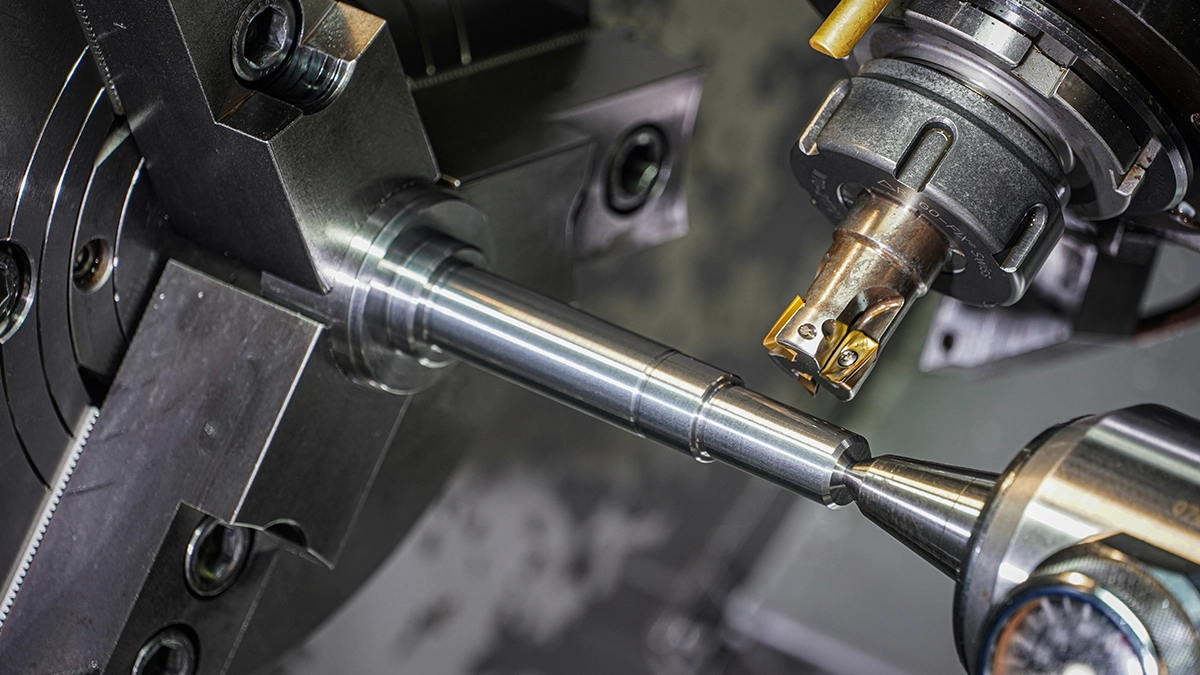
Longitudinal turning is the oldest and most frequently performed operation on a lathe: a rotating workpiece, a turning tool moved parallel to the axis, and a cylindrical surface that grows with every revolution. Behind that simplicity sits a whole technology: the entering angle, the choice of feed and cutting speed, cutting forces, tool vibration and the line between roughing and precision machining. In this guide we sort out the methods of longitudinal turning and the related types of turning, the parameters and the applications, from shafts to housings, drawing on machining textbooks and tool manufacturers' catalogues.
Longitudinal turning: what it is and how it works
Longitudinal turning is the variant of turning in which the feed motion of the tool is parallel to the axis of rotation of the workpiece. The primary motion is performed by the rotating part, held in a chuck or between centres, while the cutting tool travels along it, removing a layer of material of thickness .
The result is a cylindrical surface, external (shafts, journals) or internal (bores), when the tool works as a boring bar. Textbooks (Jemielniak, Grzesik, Olszak) define turning precisely through this kinematics: rotation of the workpiece plus rectilinear motion of the tool; the direction of that motion decides whether we are dealing with longitudinal, transverse or taper turning.
Chip removal here is continuous: the cutting edge is in contact with the material throughout the revolution, the chip has a constant cross-section and material removal proceeds evenly. That distinguishes turning from milling, where the teeth enter and leave the material. This is why CNC turning is among the most predictable operations: calculating time, forces and roughness is simpler here than in any other cutting technology.
The longitudinal motion is performed by the carriage in Z, while the infeed to depth happens in X. These two axes are enough to make a shaft, but modern CNC machines have more: a C axis for spindle positioning, a Y axis for off-centre milling, a second spindle for machining the other side. The shape of the part arises as the composition of these motions, and a program in G-code describes every pass.
Types of turning
The types of turning differ in the direction of the feed motion relative to the axis of rotation and in how the part's shape is generated. In practice several are performed on one part in one setup. Longitudinal turning methods in the strict sense differ mainly in parameters and tooling; the variants below differ in kinematics.
Transverse turning (facing)
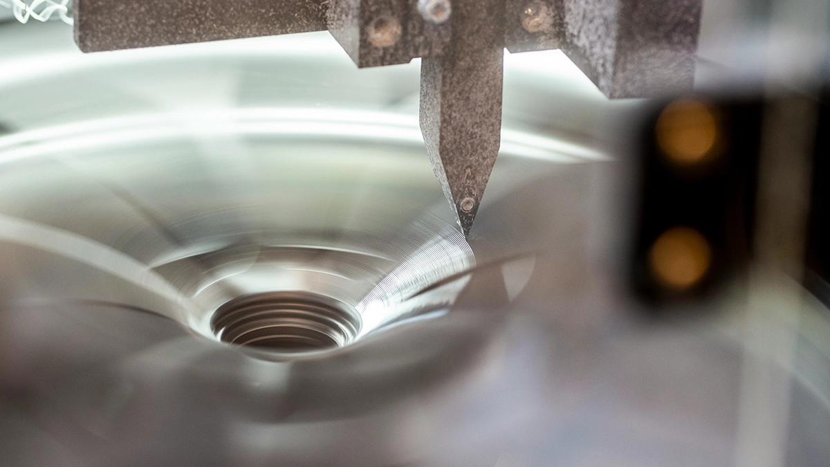
Transverse turning is a feed motion perpendicular to the axis of rotation. This is how face turning is done, facing the end of a shaft, a flange or a bushing, as well as parting off and grooving. The facing process has one important peculiarity: at constant rpm the cutting speed falls as the tool approaches the centre, down to zero in the middle of the face. That is why CNC controls offer the G96 function (constant surface speed), which raises the rpm as the diameter decreases. Without it, face turning gives an uneven result: smooth at the periphery and torn in the middle. In facing you also watch the spindle speed limit: on large flange diameters G96 may demand an rpm the machine or the chuck cannot handle.
Taper turning
Taper turning arises when the tool motion is inclined to the axis of rotation: on conventional machines by swivelling the compound slide or offsetting the tailstock, on CNC machines by linear interpolation in X and Z simultaneously. It is performed on spindle noses, tool tapers (Morse, ISO, HSK), valves and conical seals. The taper angle is a functional dimension, so taper turning on CNC is usually combined with a check on a ring gauge or by bluing.
Form turning
Form turning gives the part a profile reproduced from the shape of the tool edge: a form tool with the appropriate profile plunges radially, and the whole contour, a snap-ring groove, a radius, a chamfer, a spherical profile, is produced in one motion. It is fast in series production, but requires special turning tools and generates large forces, because a long edge works across the whole width at once. On CNC machines this method is increasingly replaced by contour interpolation with an ordinary tool, and the form tool stays where cycle time counts.
Copy turning and generating turning
Copy turning means guiding the tool along the profile of a template or, today, along a contour stored in the program; in practice every CNC turning of a stepped shaft contour is copy turning in the kinematic sense. Generating turning, in turn, is a method in which the tool rotates synchronously with the workpiece and the shape arises as the envelope of successive positions of the cutting edge. It is used to produce polygons (wrench hexagons on journals) and non-circular profiles without moving the part to a milling machine. The literature describes it as related to the generating methods of gear cutting: here too the shape is not copied from the tool but results from the composition of two motions.
Threads
Thread turning is a special case of longitudinal turning: the feed per revolution equals the thread pitch and must be rigidly synchronised with the spindle (on CNC, the G33/G76 or G92 cycle). Threads are turned in several passes of decreasing depth, infeeding the tool at the flank angle so that mainly one edge cuts. External and internal threads in CNC turning are the standard wherever a tap or die cannot cope: large diameters, trapezoidal, multi-start and non-standard pitch threads.
Applications of longitudinal turning
The applications of longitudinal turning cover practically every part with rotational symmetry. Drive shafts, bearing journals, pins, lead screws, piston rods, spindles: all of them begin life as a bar in a chuck. Bushings, rings, pulleys and valve bodies additionally require internal turning and face turning.
Machine building is the largest customer: shafts and bushings are the most common machine parts in any documentation. Next come automotive (camshafts, half-shafts, hubs), hydraulics (piston rods, cylinders), power engineering and aerospace.
The applications range from one-off to mass production: the same shaft can be made on a conventional machine in a repair shop and on a Swiss-type sliding-head automatic in a run of a million pieces. The production of precision parts, injector needles, stepper motor shafts, implant components, is also the domain of turning, only in the version we describe further on as precision turning. Longitudinal turning in metalworking covers all material groups, and the methods are matched to the material, the accuracy and the batch size.
CNC technology in turning
CNC technology changed turning more than any other operation. On a manual lathe accuracy depended on the turner's hand; CNC moved it into the program, and servo drives guide the tool repeatably to thousandths of a millimetre. CNC lathes divide into two-axis lathes (X, Z), turning centres with live tooling and a C axis, twin-spindle versions and sliding-head automatics.
In sliding-head automatics the material itself moves through a guide bushing while the tool works right next to it, ideal for long, slender parts.
Longitudinal turning methods on CNC machines rely on several functions that cannot be achieved by hand: constant on a changing diameter, roughing cycles that split the allowance into equal passes, tool nose radius compensation when turning tapers and radii, synchronised threading and automatic compensation of tool wear. The use of CAD/CAM systems closes the chain: the 3D model of the part goes to CAM, which generates the roughing, finishing and threading paths, and a postprocessor translates them into the dialect of the control. CNC technology does not eliminate the process engineer's knowledge, someone still has to choose the machining parameters and the sequence of operations, but it takes the repeatable part out of their hands. How the whole of CNC machining works from the business side we described in what CNC machining is.
Workpiece materials
Longitudinal turning is applied to all engineering materials, but each group dictates its own parameters. In the ISO 513 classification, metalworking divides workpiece materials into groups P (steels), M (stainless steels), K (cast irons), N (non-ferrous metals), S (superalloys and titanium) and H (hardened materials).
Structural steels turn predictably and give a continuous chip that has to be broken by the chipbreaker. Stainless steels work-harden under the edge and conduct heat poorly: must be large enough for the edge to cut below the hardened layer. Cast iron gives a discontinuous chip and abrasive dust; aluminium turns at high cutting speed but loves built-up edge. Group S materials, Inconel, titanium, are the machining of difficult-to-cut materials: low speeds, sharp geometries, intensive cooling and short tool lives.
Hardened materials are a category of their own. Hard turning (45-65 HRC) with CBN or ceramic inserts, as a finishing process for hardened surfaces, increasingly replaces the grinding of journals and bushings: one setup, no grinding machine, IT6-IT7 accuracy and 0.2-0.4 roughness. The use of ceramic and CBN tools, however, demands a rigid machine, a stable setup and continuous cutting; materials in this state forgive neither vibration nor an interrupted chip. More on the relationship between material and parameters in our guide on how to calculate cutting speed, RPM and feed.
Turning tools: geometry and the entering angle
Turning tools for longitudinal turning are today almost exclusively indexable: a holder with a pocket, a multi-edge carbide insert and a clamping element. Tool geometry describes the insert with several angles, rake, clearance, inclination, and the nose radius, but in longitudinal turning one angle has special significance.
It is the entering angle : the angle between the main cutting edge and the direction of feed. The entering angle decides the chip thickness, the distribution of forces, the load on the nose and the ability to turn up to a shoulder.
How the entering angle changes the process
Textbooks (Grzesik, Jemielniak) give a relationship worth remembering: chip thickness , and the width of the cut layer . At an entering angle of 90° the chip is as thick as the feed and a short section of the edge works; at 45° the same gives a chip 30% thinner, spread over a longer section of the edge. A smaller therefore means a lower load per millimetre of edge, longer tool life and the possibility of increasing without worsening roughness, but at the cost of a larger passive force , which pushes the tool away from the workpiece and bends slender shafts. That is why for parts of low rigidity a close to 90-95° is chosen (small radial forces), while for rigid, short parts turned in roughing a of 45-75° gives lower cutting forces per unit of edge length and allows a large . A value of 93-95° is the standard in longitudinal turning up to a shoulder, because it lets you face the shoulder in the same pass. Finally, it affects entry into and exit from the material: at smaller angles the nose enters the material gradually, which reduces the risk of chipping.
Inserts, holders and tooling systems
A turning tool is selected according to the ISO system: a holder such as PCLNR 2525 M12 describes the clamping method, insert shape, entering angle (letter L = 95°), hand of cut and shank section. Premium turning tools offer more than geometry today. Sandvik Coromant, the largest manufacturer in this segment, develops for example CoroTurn HP, holders with precisely directed high-pressure coolant nozzles that force fluid between the chip and the rake face, improving chip breaking and tool life in stainless steels and superalloys. CoroTurn® SL is a modular system: exchangeable cutting heads mounted on adapters with a serrated coupling, so that one holder or boring bar can be switched in seconds from longitudinal turning to grooving or threading. CoroTurn® SL also combines with the Silent Tools range, boring bars and adapters with a built-in vibration damper that allow bores to be turned at overhangs of 7-10 diameters (and up to in tuned-damper versions), where an ordinary steel bar starts to chatter at . Silent Tools solve a problem that parameters cannot get around: tool vibration at long overhang. CoroTurn® SL with Silent Tools heads is today the standard for turning deep bores in cylinders and hydraulic bodies.
Innovative tool materials change the economics of turning tools from the other side: carbide grades with PVD and CVD coatings of controlled stress, sialon ceramics for cast iron and superalloys, CBN for hardened steels. Tool wear is measured by the width of the wear land on the clearance face (VB), and tool wear management in series production means changing inserts by piece count, before the wear land shows up in the dimension and roughness. More on design and selection in our article on cutting tools.
Cutting parameters in longitudinal turning
The parameters of longitudinal turning are the classic trio: cutting speed , feed and depth of cut , and it is this trio, not the type of machine, that decides the result. They are chosen in exactly that order, but their roles differ.
Depth of cut decides the number of passes and the material removal rate; shapes the surface and the load on the edge; governs temperature and tool life. The parameters do not act in isolation: the same at a different entering angle gives a different chip, and the same with a different insert grade gives a different tool life.
Depth of cut and feed f
Depth of cut in roughing is limited by machine power, setup rigidity and insert edge length: with a CNMG 12 insert a typical is 2-5 mm, with large roughing inserts up to 8-10 mm. The roughing stage is meant to remove the allowance as fast as possible, so it works with a large and a large (0.3-0.6 mm/rev), and surface quality is secondary. Roughing leaves an allowance of 0.5-1.5 mm per side; finishing, precision turning, removes it in one or two passes at and a small (0.3-1 mm). Feed is the parameter that most affects roughness: the theoretical profile height grows with the square of (), so halving improves the theoretical profile fourfold. Below a certain limit, however, stops helping: the edge starts to rub instead of cutting, and surface quality deteriorates. Rule of thumb: in finishing not less than half the nose radius, and in roughing not more than half the radius, so that the nose does not break. Choosing and is always a compromise between productivity, tool life and the load on the system.
Cutting speed
The value of is taken from the catalogue for the material-grade pair: for carbon steels and coated carbide 200-350 m/min, for stainless steels 120-200, for cast iron 150-300, for aluminium 500-1500 m/min and more. High cutting speed shortens the cutting time and reduces the tendency to built-up edge, but according to Taylor's equation tool life falls exponentially: a 20% increase in speed can halve tool life. High cutting speed makes sense where the machine hour is expensive and the insert cheap; with expensive special tools and difficult-to-cut materials you go lower. In interrupted cutting (keyways, cross holes in a shaft) is reduced by 20-30% and an insert with a tougher nose is chosen. High rpm also demands a stable setup: at 3000 rpm an unbalanced flange generates vibration no chipbreaker can hide.
Optimising the cutting parameters
Optimising the cutting parameters in longitudinal turning starts from one textbook rule: first the maximum depth of cut, then the maximum , and last. Depth and raise the removal rate () with almost no effect on tool life, at the expense of tool life. Optimisation is then a search for the minimum of the sum of tool cost and machine time cost: the economic speed lies below the speed of maximum productivity. In practice it is iterative: you log the pieces per edge, inspect the wear under a loupe and correct one parameter at a time, watching machining quality and tool life. Optimisation at the program stage delivers more than buying a new machine: in series turning a 15-20% cycle improvement with no investment is the rule, not the exception. If the most expensive minute in CNC machining is the one when the machine stands still, the second most expensive is the one when it cuts too slowly.
Use of coolant
The use of coolant in longitudinal turning has three purposes: removing heat from the cutting zone, lubricating the chip-edge contact and flushing away chips. In carbon steels with coated carbide, turning is often done dry or with minimum quantity lubrication; in stainless steels, titanium and superalloys high-pressure coolant (70-80 bar, systems like CoroTurn HP) can extend tool life by tens of percent and force the breaking of a continuous chip. With ceramics and hard turning coolant is usually not used: thermal shock cracks the insert.
Precision CNC machining: finish turning, tolerances and surface quality
Precision finish machining is not just a smaller ; the quality of finishing is built on several conditions at once. Precision turning requires a rigid machine in a good thermal state, a balanced setup, a sharp insert with a small nose radius and dimensional control between passes.
Finish turning on a good turning centre achieves dimensional tolerances of IT7-IT8 and a roughness of 0.8-1.6; precision turning with wiper inserts (with a modified nose profile that flattens the peaks of the irregularities) gives 0.4-0.8 at twice the of a standard insert. Finish hard turning with CBN inserts reaches IT6 and 0.2, a level that a decade ago was reserved for grinding. Precision turning demands consistency, though: the same insert, the same , the same allowance for the finishing pass, because every change alters the load and therefore the deflection of the shaft and the dimension.
Precision CNC machining in longitudinal turning most often runs into two problems: workpiece deflection and taper error. A slender shaft between centres deflects under the passive force most at mid-length, hence a close to 90°, a steady rest and small in the finishing pass. Taper arises from misalignment of tailstock and spindle and from tool deflection, and it is corrected by measuring the part at both ends after the first pass. Precision CNC machining therefore means measurement built into the cycle: workpiece probes measure the diameter after the roughing pass and correct the tool offset before the finishing pass. Finish turning in series also means managing heat: the first pieces after warming up the machine have a different dimension from the hundredth, so good shops warm up the spindle and compensate for drift. Which dimensional tolerances really cost money and which can be loosened we described in tolerances and machining cost.
Surface quality after turning
Surface quality after longitudinal turning is described above all by the roughness and . The workpiece surface after turning has a characteristic directional helical mark whose pitch equals the feed, which is why roughness is measured perpendicular to the marks, along the generating line. Surface quality is affected, in order, by: feed and nose radius (the theoretical profile), tool wear (the wear land on the clearance face prints itself onto the surface), built-up edge at too low a , vibration and system rigidity. Surface quality deteriorates abruptly when the insert exceeds its critical wear, one of the most sensitive signals to change the edge. Surface finishing can also be the last operation: roller burnishing after turning compacts the surface layer and gives 0.1-0.2 without grinding. How to read and requirements on a drawing we explain in our article on surface roughness.
Cutting forces and vibration
Cutting forces in turning are resolved into three components: the main force (tangential, determining power), the feed force and the passive force . They grow in proportion to the cross-section of the cut layer and depend on the material through the specific cutting force ; lower cutting forces are obtained with positive insert geometry, a sharp edge and, paradoxically, a larger at a smaller depth, because the specific cutting force falls with chip thickness. Lower forces mean less shaft deflection, less vibration and better machining quality. Vibration appears, and prints itself onto the workpiece surface, when the rigidity of the system cannot keep up with the load: at long boring bar overhang, a thin-walled ring in the chuck or a slender shaft without support. The remedies, in order, are: smaller , larger (a thicker chip stabilises), a change of , a smaller nose radius, support, and in deep bores Silent Tools instead of an ordinary boring bar. The use of process monitoring systems (spindle power measurement, vibration sensors) detects edge wear and vibration before the operator sees them.
Production automation in turning
Production automation in turning is easier than in most other cutting technologies, because the bar stock is ready to be fed by its very nature. A bar feeder with automatic parting, a gripper collecting the finished part, a second spindle for the other side and a chip conveyor form a cell that runs without an operator for a whole shift.
Automation on sliding-head automatics goes further: a dozen or more tools on several slides work simultaneously, and the part leaves the machine completely finished, with threads, grooves and milled features.
The use of adaptive control systems is the next level: the system measures spindle power or load in real time and corrects so that the load on the edge stays constant regardless of the varying allowance of a forging or casting. In the roughing of forgings, adaptive control shortens cycle time by 10-30%, because no longer has to be chosen for the worst case. The use of process monitoring systems closes the loop: detection of a broken insert stops the cycle, and the power trend predicts the end of tool life. Productivity in an automated cell is measured no longer by cycle time but by the number of good parts per day, and that is where the value of well-chosen machining parameters shows.

CNC turning services: when to outsource
CNC turning services are the most frequently purchased subcontracting service in metalworking, for a simple reason: almost every machine contains shafts and bushings, and not every company has its own turning capacity. Turning services are offered both by small workshops with two machines and by large production plants using spare capacity.
An example of the second group is CPP PREMA, a pneumatics manufacturer from Kielce, Poland, which, beyond its own product range, provides specialised CNC turning services to external customers. When choosing a turning service, check three things: the machine park (is there a turning centre with live tooling and a sub-spindle, so the part comes out in one setup), quality control (gauges, a roughness tester, possibly a CMM) and experience in the given material; turning stainless steel and titanium is a different league from turning free-cutting steel.
The price of such a service follows from what we described above: the cutting time (allowance volume divided by the removal rate at the given parameters), the setup time spread over the batch, the number of setups and the accuracy requirements. A shaft turned to general tolerances and a shaft with h6 bearing journals are two different processes; the second has an extra finishing pass, measurement and often grinding. The complete process plan for a shaft with h6 journals, operation by operation, is shown in a separate article. In MetronQ quoting the geometry of a rotational part is recognised automatically: the engine detects cylindrical surfaces, tapers, threads and grooves, converts them into roughing and finishing time with realistic parameters, and tolerances and roughness act as time multipliers set by the shop. The customer sees the price within a minute, with price breaks for different quantities; the cost of the tool for a shop is in the pricing. The full price breakdown from the buyer's side - rates, materials, batches and example quotes - is covered in our guide to machining quotes.
Frequently asked questions about longitudinal turning
What is longitudinal turning?
Turning in which the tool motion is parallel to the axis of rotation of the workpiece; it produces an external cylindrical surface (shafts, journals) or an internal one (bores, bushings). It is the basic lathe operation and the starting point for most rotational parts.
What are the types of turning?
By direction of tool motion: longitudinal, transverse (facing, parting) and taper turning; by the way the shape is generated: form, copy and generating turning; thread turning and hard turning are distinguished separately. On CNC machines several of them are performed in one cycle.
What is the difference between rough and finish turning?
Purpose and parameters. Roughing removes the allowance with a large and , ignoring the surface; finish turning removes the last tenths of a millimetre with a small and a sharp insert to hit the tolerance and the required roughness. Separating the two stages limits the effect of forces and heat on the result.
Which entering angle should I choose?
For turning up to a shoulder and for slender shafts 90-95°, because it gives the smallest passive force and lets you turn the shoulder. For rigid parts and roughing 45-75°: a thinner chip, longer tool life, a larger permissible . A value below 90° increases the radial force, so it is unsuitable for thin shafts without support.
How do I choose the parameters for longitudinal turning?
From the insert manufacturer's catalogue for the material-grade pair, then correct at the machine. Roughing 0.3-0.6 mm/rev, finishing 0.08-0.2 mm/rev; for steel with carbide 200-350 m/min. The rpm follows from , where is the workpiece diameter; our free cutting parameters calculator does this conversion and shows the formula with your numbers.
What accuracy does CNC turning give?
Typically IT7-IT8 and 0.8-1.6; precision turning with wiper or CBN inserts on a rigid machine reaches IT6 and 0.2-0.4, which allows grinding to be skipped in many applications. The conditions are thermal control of the machine and in-cycle measurement.
Where does vibration in longitudinal turning come from and how do I remove it?
From insufficient system rigidity relative to the loads: long overhang, thin walls, a slender shaft. Smaller , larger , a close to 90°, a smaller nose radius, support with a steady rest, and for deep boring damped bars such as Silent Tools all help.
When hard turning instead of grinding?
When the part is hardened to 45-65 HRC, has simple rotational geometry and requires IT6-IT7 with 0.2-0.4. CBN turning in one setup is then faster and cheaper than a grinding machine, provided the machine is rigid and the cut continuous.
Sources
- 1.K. Jemielniak, "Obróbka skrawaniem", Warsaw University of Technology Press (turning kinematics, edge geometry, cutting forces)
- 2.W. Grzesik, "Podstawy skrawania materiałów konstrukcyjnych", WNT (entering angle, chip thickness, Taylor's equation)
- 3.W. Olszak, "Obróbka skrawaniem", WNT (types of turning, parameter selection)
- 4.R. Wołk, "Normowanie czasu pracy na obrabiarkach do obróbki skrawaniem", WNT, Warsaw 1972 (lathe tables)
- 5.Sandvik Coromant, "Training Handbook: Metal Cutting Technology" (CoroTurn HP, CoroTurn SL, Silent Tools, recommended parameters)
- 6.ISO 513 (workpiece material groups)
- 7.ISO 286 (IT tolerances).
Read next
Automatic CNC machining quotes
Priced from the 3D model or the drawing, on your machines and your rates. You just approve it. 14 days free, no card.
Create a free account