Depth of Cut: Selection, Calculation and Values
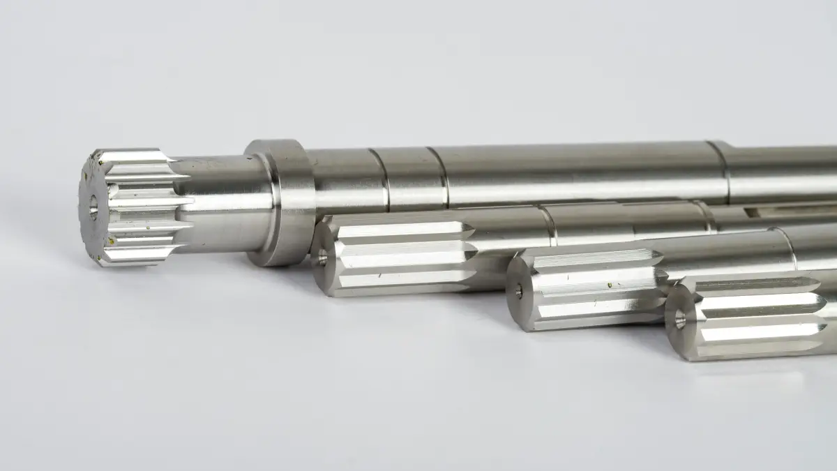
Of all the values a process engineer sets on a machine tool, depth looks like the simplest: how many millimetres of material the tool takes in one pass. Yet it is depth that most often decides whether a part comes off the machine in three passes or ten, whether the insert survives the shift and whether the spindle can cope at all. This guide shows how depth of cut is defined, how to calculate it from diameters, how to match it to the insert, cutter and machine - and how to tell when it is too deep or too shallow.
Depth of cut ap: definition and units
Depth of cut is the thickness of the material layer removed in one pass, measured perpendicular to the feed direction. ISO 3002-1 and tooling catalogues denote it and give it in millimetres. In longitudinal turning, depth of cut tells you how much the part's radius shrinks in one pass - not its diameter, which is beginners' mistake number one.
In milling, is the axial depth measured along the cutter axis, and a second quantity joins it: the radial depth of cut , the width of the band of material the cutter takes with its periphery.
Both are expressed in millimetres. Depth sets the thickness of the cut layer, feed sets its width in the direction of motion; the product of the two is the chip cross-section that the edge, the workpiece and the whole machine have to handle. That is why choosing the depth of cut always starts with the allowance and rigidity, not with a table.
Depth also defines the type of operation: a few millimetres means roughing, a few tenths means finishing to size. Shop documentation writes it as depth per side (e.g. ), which makes it clear that it refers to the radius, not the diameter. A workpiece with a large allowance therefore needs a completely different plan from a shaft turned almost to size.
The cutting edge and the cross-section of the cut
The part of the tool actually in the material is the cutting edge, and its engaged length depends on depth and on the lead (entering) angle . At degrees the engaged edge length equals ; at degrees the same depth spreads over an edge about 41% longer, and the chip becomes thinner and wider. Maximum chip thickness in turning is - depth does not appear in that formula, but it determines how long a section of the edge is loaded and how much heat goes into the insert.
Hence the first practical limit: depth of cut must stay within the range the insert geometry was designed for. Manufacturers give an - window for every chipbreaker; outside it the chip stops breaking or the edge is overloaded. As a guide, the maximum depth for a turning insert is 1/2 to 2/3 of the edge length (depending on insert shape), and the minimum is no less than about 2/3 of the nose radius . We cover edge and insert design in our overview of cutting tools. Modern inserts have these windows encoded in the chipbreaker designation (e.g. -PM, -MR), so choosing a depth starts with reading the insert code.
Basic cutting parameters and depth
The basic set consists of three quantities: cutting speed , feed and depth . Together they describe the cutting process in every operation - from turning a shaft to milling a pocket - and everything else follows from them: forces, temperature, tool wear and time.
Formulas for the full set, starting tables and step-by-step examples are in our separate guide on how to calculate cutting parameters; here we deal only with the third one. Feed has its own guide too: feed rate - per revolution, per tooth and per minute.
Why does depth deserve its own article? Because of the three quantities it has the weakest effect on tool life and the strongest effect on the number of passes. Cutting speed affects wear exponentially, feed noticeably, depth the least. In the extended Taylor equation the exponent for is usually several times smaller than for : doubling depth shortens tool life by some tens of percent at most, doubling speed shortens it several times over. This holds across metal cutting, from steel to titanium, and it produces the classic rule repeated in textbooks from Grzesik to Stephenson: first the largest possible depth, then the largest possible feed, and only at the end the cutting speed chosen for the required tool life. The same order applies whether you are turning, milling or drilling.
Calculating depth of cut: formula and example
In turning, is half the diameter difference before and after the pass, because the tool cuts on both sides of the axis at once: a 60 mm shaft turned to 52 mm gives 4 mm. Facing counts the layer taken off the face, boring flips the formula, and in milling the allowance is split into layers.
In turning there is one formula, and it is worth knowing by heart:
where:
- - diameter before the pass [mm] (the workpiece diameter),
- - diameter after the pass [mm] (the machined diameter).
The division by two comes from the tool removing material on both sides of the axis at once. The starting diameter is measured before the pass, not read off the drawing - stock is often oversize. For a 60 mm shaft turned to 52 mm, . If that allowance is removed in two passes - 3.5 mm roughing and 0.5 mm finishing - each pass has a different depth, and the total number of tool passes is two.
In facing, calculating the depth is even simpler: it is just the thickness of the layer taken off the face, measured along the axis. In boring the formula reverses - the machined diameter is larger than the starting one, so . In milling, calculating depth comes down to splitting the allowance into layers: an 18 mm deep pocket at is three layers, at four.
One subtlety is worth remembering. The actual cutting speed at the bottom of the layer is lower than at its top, because the diameter shrinks: on a 60 mm workpiece with , at the 52 mm diameter drops by about 13%. For a roughing pass that does not matter, but with deep cuts on small diameters - turning journals, for instance - the difference can push conditions outside the chipbreaker window. Since cutting speed depends on diameter and rpm, every change of depth on a small part changes the conditions at the edge. A control running constant surface speed (G96) computes rpm for the diameter at the tool tip, so the actual cutting speed at the outer edge of the layer is higher than programmed.
Actual depth of cut versus the programmed value
The actual depth of cut differs from the programmed one more often than you would think. The culprit is elastic deflection of the machine - chuck - workpiece - tool system: a slender shaft bends under the passive force, a cutter on a long overhang deflects away from the wall, and a worn edge "pushes" material away. The result: after a pass to the target diameter, measurement shows a few hundredths too much, and the next "zero" pass takes an actual depth of 0.02-0.05 mm - below the healthy minimum.
The opposite happens on castings and forgings: the allowance is uneven, so the actual depth varies along the pass, sometimes several-fold. Hence the rule that the first pass on raw stock is planned so that the edge cuts beneath the skin along its whole length - the condition of the material (scale, hard casting skin, sand inclusions) decides what the smallest safe depth is. Compare cold-drawn bar with a forging: the surface condition differs, so the minimum must differ too. After the first pass the machined surface is uniform and the following layers can be planned without a margin.
Depth of cut in turning: turning parameters step by step
Turning parameters are chosen in a fixed order: depth first, then feed, speed last. Depth should follow from the allowance and the number of passes you want; feed per revolution from the required roughness and insert strength; speed from the material and the required tool life.
This order gives the shortest machining time for a given tool life, because it shifts the load onto the parameter that tool life treats most gently.
On an ordinary CNC lathe, depth should be chosen so that the number of roughing passes is as small as possible, leaving 0.2-1 mm per side for finishing. For structural steel and a CNMG 12 insert, typical settings are: , , . When turning long shafts, depth is limited by workpiece rigidity rather than by the insert; when facing large diameters, by spindle power. On the operation sheet the process engineer writes the depth for each pass so that the operator does not have to reconstruct it from the program.
Recommended machining parameters always assume a specific insert grade and geometry, which is why the same values differ between two manufacturers' catalogues. One rule is common to all: with the same insert, a larger depth increases force proportionally but barely changes edge temperature - the heat spreads over a longer edge. A larger depth also increases the passive (radial) force, which on slender shafts leads to vibration sooner than the power increase does. That is why in longitudinal turning productivity reserves are sought in depth first.
Recommended depth of cut: roughing, semi-finishing and finishing
The recommended depth depends on the stage, i.e. on the type of operation:
| Stage | Depth of cut, mm (turning steel) | Feed per revolution , mm/rev | Goal |
|---|---|---|---|
| Roughing | 2-6 (up to 10 on heavy lathes) | 0.3-0.6 | remove stock as fast as possible |
| Semi-finishing | 0.5-2 | 0.15-0.3 | even out the allowance before finishing |
| Finishing | 0.2-1 | 0.05-0.2 | size, tolerance, roughness |
Roughing is about removing material, so roughing depth is limited mainly by power, rigidity and edge length. Semi-finishing evens out the allowance so that the final pass works at a constant, predictable depth. Finish machining, which has its own article, works at small depths - but not arbitrarily small ones: below about 0.1 mm the edge starts ploughing instead of cutting.
Treat the values in the table as a starting point. Difficult-to-cut materials follow their own rules: in stainless steel the roughing is usually kept and is reduced; in aluminium depth can be increased substantially, because forces are about three times lower. The insert manufacturer's catalogue gives recommended values for each grade - and it is the final authority, listing suitable cutting speeds for each material group (P, M, K, N, S, H) separately for roughing and finishing depths. After the first part, settings are corrected by chip and sound.
Depth of cut in milling: ap, ae and chip thickness
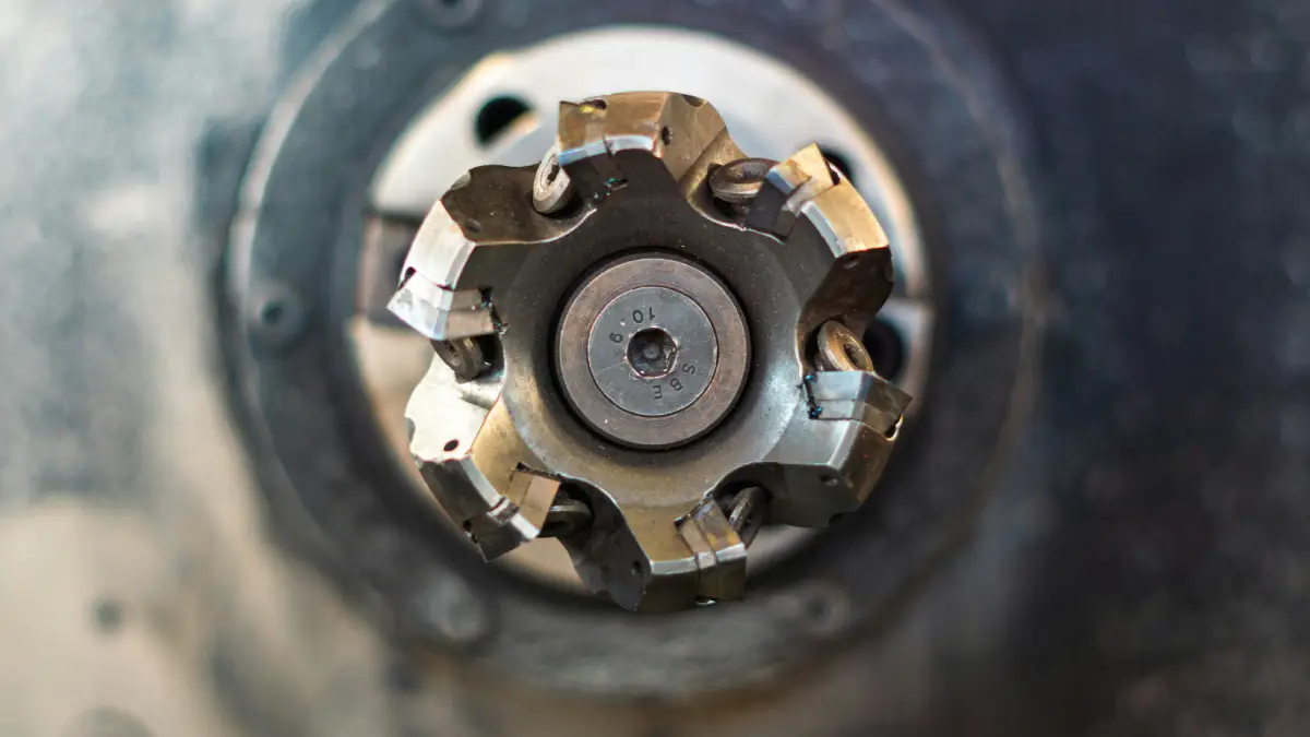
In milling two depths come into play: axial and radial . Their ratio defines the strategy. Full slotting means (the full cutter diameter) and usually no more than ; peripheral milling means small and large , even ; face milling means large and limited by insert edge length.
Depth with solid-carbide end mills is therefore chosen quite differently from depth with indexable cutters. With indexable inserts, depth should leave a margin of about 10-20% of the edge length so that the corner is not working at its limit. For solid end mills depth is often given as a multiple of the diameter (e.g. ), and recommended parameters as - pairs. Side-and-face (disc) cutters follow yet another logic: the depth corresponds to the slot height and the width to the disc thickness.
Radial depth has an effect with no counterpart in turning: it changes chip thickness. When falls below half the diameter, the tooth enters the material tangentially and the maximum chip thickness is smaller than the feed per tooth : . Average chip thickness falls even further - approximately . At of diameter, is only about 44% of , so a small radial depth calls for a higher feed per tooth to keep the chip above about 0.02-0.04 mm. We describe this chip-thinning correction in detail in the feed article - what matters here is that the feed correction follows directly from the radial depth.
Ball-nose milling adds a third relationship: at small the cutter does not cut with its nominal diameter but with the effective diameter at the contact point. That cutting diameter at a given depth is ; a 10 mm ball-nose cutter at cuts with a diameter of only 4.4 mm. The actual cutting speed drops by more than half, so raising the rpm to correct cutting speed is mandatory - a high cutting speed at the contact point is a precondition for a good surface. With ball-nose cutters, depth therefore determines not just productivity but the cutting conditions at the edge.
Circular milling (circular interpolation) changes the effective radial depth: on internal arcs at the edge is larger than on a straight pass with the same programmed value, because the hole's arc "wraps" around the cutter. That is why depth is chosen more cautiously when circular-milling pockets than on external contours, and table feed is corrected by the diameter ratio.
Excessive depth of cut - and too little: symptoms and consequences
Excessive depth of cut produces symptoms every operator knows by ear. The first is vibration: the passive force rises, a slender workpiece or an overhanging cutter starts to chatter, and characteristic bands appear on the machined surface. The second is spindle overload - rpm dropping under load, a power alarm, in the extreme case a stall. The third is edge chipping: at depths beyond the engaged edge length, the insert cuts with its corner and a section never meant for cutting.
Excessive depth also threatens accuracy: elastic deflection grows with force, so the actual depth departs from the programmed one and the size "drifts" along the part. Too much depth on thin walls ends in distortion - the workpiece bends under the tool and springs back once unclamped, taking the dimension with it. The remedy is nearly always the same: split the allowance into more passes, or change the lead angle to 90-95 degrees, which directs the force along the axis rather than sideways.
Too little depth is dangerous in a less obvious way. When drops below the edge hone radius (typically 0.02-0.05 mm), the edge stops shearing and starts sliding over the material, work-hardening it and accelerating tool wear. Too shallow a cut in stainless steel is a recipe for a hard skin in which every following pass works worse - here the culprit is depth, not speed. A third trap: with a large nose radius, too little depth means the chip forms only on the radius and does not break - the ribbon wraps around the part.
Selecting cutting parameters: depth, feed and cutting speeds
Choosing the depth is the first step, but not the only one: a change in drags corrections to the other values with it. Cutting speed depends mainly on the material-edge pair and the required tool life, but also on chip cross-section: for heavy sections, catalogues recommend reducing cutting speed by a few to a dozen or so percent.
Cutting speed also has a minimum: below about 60-80 m/min in steel the risk of built-up edge rises. Keep in mind that the actual cutting speed at large depth on a small diameter is lower than the catalogue value, which partly compensates for the higher load by itself. Suitable cutting speeds for carbon steel with coated inserts are roughly 180-300 m/min; for stainless steel 120-200 m/min; for hardened steel with CBN 100-200 m/min, but at depths of 0.1-0.3 mm. What cutting speed depends on and how to correct it is covered in our guide on cutting speed.
High cutting speed works well with small depth: that is how finishing and HSC milling operate. Large depth, on the other hand, prefers moderate speed: a large chip section generates more heat, so higher speeds would shorten tool life disproportionately. Under such conditions cutting speed also depends on how effectively the coolant removes heat from the cutting zone. High speed at large depth makes sense only on very rigid machines with spare power - and even there the speed is chosen last, after depth and feed.
In milling the chain is longer: depth and width determine chip thickness, chip thickness determines the feed per tooth , and that gives the feed speed , where is the effective number of teeth engaged at once. Feed speed and rpm are the only numbers the control sees in the program; everything else is hidden in how they were chosen. That is why settings are always recorded as a complete set - , , , - never individually.
The order rule has one exception: high feed with small depth (high-feed milling, HFM). Cutters with a small lead angle (about 10-15 degrees) thin the chip so much that rises to 1-2 mm while drops to 1-2 mm. The high feed then directs the force axially towards the spindle, which allows long overhangs without vibration. Productivity can be higher than with the classic deep strategy.
Metal removal rate Q, forces and power
Metal removal rate is the volume of material removed per minute. In turning (cm3/min), in milling . Depth enters both formulas linearly - doubling doubles the removal rate at almost unchanged tool life, something no other parameter manages.
Cutting speed carries the same weight in the formula, but costs far more tool life. Every extra millimetre still has a price: depth increases force and power linearly. Watch the units: comes out in cm3/min when is in m/min and and in mm - cutting speed entered in mm/min would give a result a thousand times too large. That is why roughing productivity is measured in cm3/min, not in rpm or mm/min.
You pay for removal rate in force and power, and a deep cut requires checking both. Cutting force , where the specific cutting force depends on the material and chip thickness (about 1,700-2,100 N/mm2 for structural steel, 600-900 N/mm2 for aluminium). Light alloys therefore allow depths at the same power that are unattainable in steel. Cutting power (kW). Example: C45 steel, , , , : , , . With a drive efficiency of about 0.8, the spindle needs at least 8.5 kW - and at the rpm at which the drive actually delivers that power.
Here lies the most common trap: spindle speed for a large diameter is low, and many drives do not reach rated power at low rpm. A deep cut on a large diameter can therefore stall a spindle that has spare power "on paper". Also remember that depth does not change the specific cutting force - depends on chip thickness, i.e. on feed and lead angle, not on . That is one more reason why depth is the cheapest route to productivity: force rises linearly, with no penalty for a thin chip.
Symbols and units: a cheat sheet
The table lists the symbols used in this guide: and in mm, diameters and in mm, in m/min, in rpm, feeds in mm/rev, in mm and in mm/min, plus , , in N, in N/mm2, in kW and in cm3/min, all following ISO 3002-1.
| Quantity | Symbol and unit |
|---|---|
| Depth of cut (axial) | , mm |
| Radial depth of cut (width of cut) | , mm |
| Workpiece diameter before the pass | , mm |
| Machined diameter after the pass | , mm |
| Cutting speed | , m/min |
| Spindle speed | , rpm |
| Feed (general) | , mm/rev |
| Feed per revolution | , mm/rev |
| Feed per tooth | , mm |
| Feed speed (table feed) | , mm/min |
| Effective number of teeth | |
| Maximum chip thickness | , mm |
| Average chip thickness | , mm |
| Cutting force | , N |
| Specific cutting force | , N/mm2 |
| Cutting power | , kW |
| Metal removal rate | , cm3/min |
| Effective cutting diameter (ball-nose cutter) | , mm |
The notation follows ISO 3002-1 and the catalogues of Sandvik Coromant, Walter and Dormer Pramet. Older tables sometimes give cutting speed in mm/s or m/s (in grinding) - convert it to m/min before using the formulas. If a CAM sheet shows cutting speed in mm/min, it is almost certainly a unit error. We use the same notation across all our guides, so values can be carried between them without conversion.
Depth of cut in CNC machining practice and quoting
In an NC program, depth rarely appears directly: the control sees coordinates, and results from the difference between successive passes. In roughing cycles (e.g. G71 on Fanuc lathes) depth is a cycle parameter - in the two-block format it is the U address in the first block - while in CAM it is entered as strategy parameters (step-down, step-over).
CAM tool libraries store recommended values for each tool-material pair, but they are only a starting point. CNC machining parameters set in CAM follow the same logic as manual ones: depth and width first, then feed, rpm last. Good CAM systems also keep constant in corners, because a varying radial depth in a pocket corner is the most common cause of broken end mills.
For the record: CNC machining does not change the physics of cutting, it only changes how precisely it can be repeated. Rigid CNC machines allow deep cuts without vibration; lighter ones require splitting the allowance into more layers. The same parameters on two machine tools will therefore give different machining times, which translates directly into part cost.
This is where depth meets economics. The number of passes follows from the allowance divided by , and machining time from the number of passes and the feed. If a better depth lets you go from four passes to two, machine time drops by almost half - and so does the part price. If you price parts more often than you calculate parameters, instant CNC quoting calculates the part cost directly from the 3D model.
Frequently asked questions about depth of cut
What depth of cut is used in finish turning?
Usually 0.2-1 mm per side, but no less than about 2/3 of the insert nose radius. With a 0.4 mm radius the minimum is about 0.25-0.3 mm; below it the edge ploughs instead of cutting and quality falls. Suitable cutting speeds here are higher than in roughing - small depths go hand in hand with high cutting speed.
What are the basic cutting parameters and where does depth fit in?
Cutting speed, feed and depth. Depth is set first, because it has the weakest effect on tool life and the strongest on the number of passes. Feed comes second, speed last - chosen for the required tool life and quality. This order applies to turning, milling and drilling alike.
Does multi-axis milling change how depth is selected?
Yes. Multi-axis milling lets you tilt the tool so that a ball-nose cutter works with its flank rather than its tip - the effective cutting diameter grows and the rpm can be lowered. In 5-axis machining with barrel cutters, the large effective radius also allows a wider stepover at the same surface quality.
What does machining in depth layers mean?
It means splitting the total depth into several layers of constant (step-down in CAM). Layered milling of deep pockets protects the tool against overload and vibration; modern dynamic strategies do the opposite - large over the full flute length and small , which uses the edge better.
How does depth of cut build an efficient machining process?
Through the number of passes: an efficient process removes the allowance in as few passes as possible at acceptable tool life. Because depth loads tool life the least, the search for reserves starts with it, and feed and speed are improved only afterwards.
What is the maximum depth of cut?
As much as the weakest link allows: the insert (about 1/2-2/3 of the edge length), spindle power, rigidity of the part and workholding, and the condition of the material. The maximum depth for a specific insert is given in the catalogue next to the chipbreaker code. In practice, rigidity rather than the tool is most often the limit.
Sources
- 1.D.A. Stephenson, J.S. Agapiou, "Metal Cutting Theory and Practice", 3rd ed., CRC Press, 2016 (cut cross-section, forces, power and tool life as a function of ap)
- 2.W. Grzesik, "Podstawy skrawania materiałów konstrukcyjnych", WNT, 2010 (definitions of ap and ae, extended Taylor equation)
- 3.K. Jemielniak, "Obróbka skrawaniem. Podstawy, dynamika, diagnostyka", Warsaw University of Technology Publishing House, 2018 (vibration and depth of cut)
- 4.S. Kalpakjian, S.R. Schmid, "Manufacturing Engineering and Technology", 8th ed., Pearson, 2020 (removal rate and cutting power)
- 5.Sandvik Coromant, "Training Handbook: Metal Cutting Technology", 2017 (hex, hm, ball-nose cutting diameter, recommended ap ranges)
- 6.ISO 3002-1 (basic quantities in cutting)
- 7.Walter and Dormer Pramet 2026 technical catalogues
Read next
Automatic CNC machining quotes
Priced from the 3D model or the drawing, on your machines and your rates. You just approve it. 14 days free, no card.
Create a free account