CNC Milling: Types, Methods and Parameters
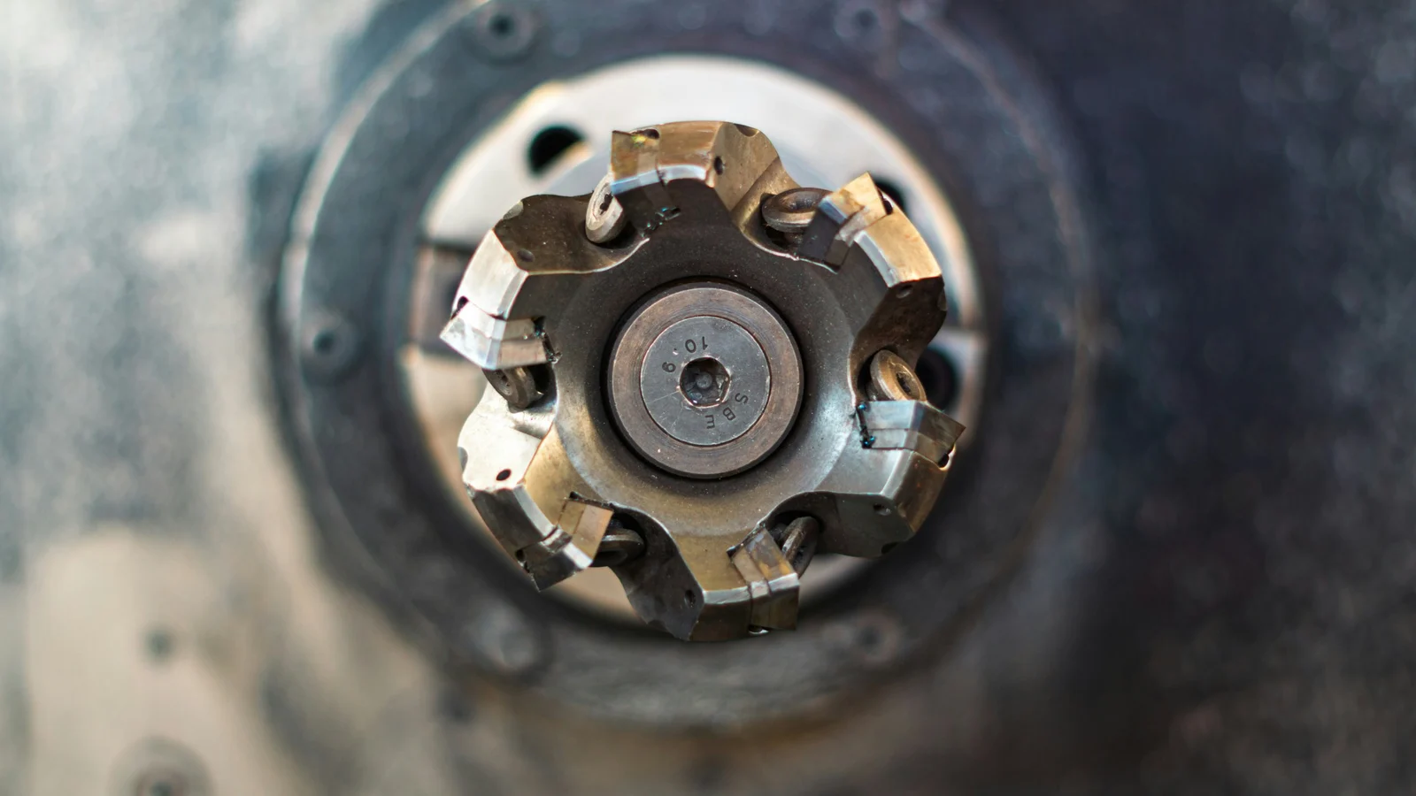
CNC milling is a machining process in which a rotating multi-tooth tool, the milling cutter, removes material from the workpiece while a program-controlled machine produces the feed motions. It creates flat faces, shoulders, slots, pockets, contours and 3D surfaces, which covers most prismatic parts. The choice of method, milling direction and number of setups decides the quality, time and price of a part.
How milling works
Milling removes material with a multi-tooth tool that rotates, which is the primary motion, while the workpiece or the spindle moves in a feed motion. Each tooth cuts for only part of a revolution: it enters the material, removes a chip and leaves. This is an interrupted cut, unlike the continuous cut in turning.
This interrupted action shapes the whole process. Every entry of a tooth into the material is a shock load, so tool life depends on how the edge enters and leaves the cut, not only on speed and feed. At the same time several teeth share the work, so a cutter can remove a lot of material with a moderate load on each edge.
According to the handbook by Swift and Booker, milling is used for all metals and for some plastics and ceramics. The process is flexible and needs little dedicated tooling, so it suits mainly one-offs and small batches. Its weak point is material utilisation: the stock turns largely into chips, and the material cost is based on the block, not on the finished part.
Milling or turning
The choice between milling and turning follows from the shape of the part. Rotational parts such as shafts, bushes and discs are turned, because the workpiece rotates about its own axis and a single edge generates a cylindrical surface. Prismatic parts such as housings, plates and brackets are milled, because their surfaces are flat or freely shaped.
Many parts combine both shapes, for example a shaft with a keyway or a disc with holes on a pitch circle. Such parts are machined on lathes with driven tools or on mill-turn centres, which allows the part to be finished in one setup. Turning parameters and tools are covered in our article on longitudinal turning.
Peripheral milling and face milling
Milling is divided into peripheral and face milling according to which part of the cutter generates the surface. In peripheral (slab) milling the cutter axis is parallel to the machined surface and the teeth on the periphery cut. In face milling the axis is perpendicular to the surface, and the teeth on the end of the tool generate it.
Swift and Booker link these variants to machine types. Horizontal milling machines are used for slab milling, form milling, slotting, gang milling and slitting. Vertical milling machines are used for face milling, slotting, dovetails and Woodruff keyways.
In practice an end mill often cuts with both parts at once. When milling a 90 degree shoulder, the periphery generates the wall and the end generates the floor. What matters on the drawing is therefore not the name of the operation but which surfaces the tool has to produce and how it can reach them.
Down milling and up milling
Down milling and up milling differ in the direction of the feed relative to the cutter rotation. In down (climb) milling the workpiece moves with the teeth in the cutting zone; in up (conventional) milling it moves against them. This small difference changes chip thickness, force direction, tool life and surface quality.
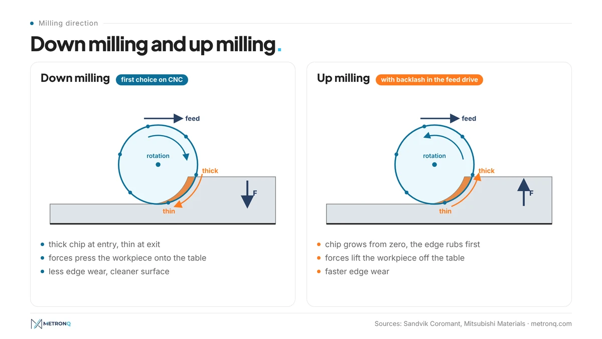
In down milling the edge enters the material at the maximum chip thickness and leaves at a thickness close to zero. Sandvik Coromant calls this the golden rule of milling: thick chip at entry, thin chip at exit. The edge starts cutting at once instead of sliding, and the cutting forces press the workpiece towards the cutter and the table.
In up milling the chip thickness grows from zero to its maximum. At the start the edge cannot bite into the material, so it rubs and burnishes the surface, which is often already work-hardened by the previous tooth. Mitsubishi Materials describes this section as a rubbing zone in which the force on the flank face rises sharply and edge wear accelerates.
Why down milling is the first choice
According to Sandvik Coromant, down milling is always preferred wherever the machine tool, fixture and workpiece allow it. The edge wears less, heat leaves with the thick chip, and the chip falls behind the tool, so it is not recut. Material from the student machine shops of Washington University in St. Louis also points to a cleaner surface and longer tool life.
The condition is a feed drive without backlash. In down milling the forces pull the workpiece under the cutter. On an old manual mill with play between the lead screw and the nut, the table can jump forward, the feed per tooth rises for a moment and the insert can chip. CNC machines usually have preloaded ball screws with practically no backlash, which is why down milling is the standard there.
When to use up milling
Up milling is justified in a few specific situations. Sandvik Coromant recommends it when the machine has no backlash elimination, when the machining allowance varies widely, and with ceramic inserts in heat-resistant alloys, because ceramics are sensitive to the impact of entering with a thick chip.
The milling direction also changes what the fixture has to do. In up milling the radial forces tend to lift the workpiece off the table, so the fixture must resist lifting. In down milling it must resist pulling forces. A thin plate held only at its edges can behave quite differently depending on the feed direction.
Types of milling and operations on a CNC mill
A CNC milling machine performs a dozen or so typical operations, each with its own type of tool. The most common are face milling of flat surfaces, shoulder milling, slotting, pocketing and contouring, 3D surface machining, chamfering, and circular milling of holes and threads. The table matches the operations with the tools usually used for them.
| Operation | Typical tool | What to watch |
|---|---|---|
| Face milling of a flat surface | indexable face mill, 45° entering angle | diameter 20-50% larger than the width, off-centre entry |
| 90° shoulder | end mill, 90° shoulder cutter | wall squareness to the floor |
| Slot | end mill, side and face cutter | full engagement, chip evacuation |
| end mill | corner radius ≥ cutter radius | |
| External contour | end mill | deflection of a long cutter |
| 3D surface | ball nose end mill, corner radius end mill | cusp height between toolpaths |
| Chamfer | chamfer mill | varying cutting diameter on the cone |
| Hole or thread by circular interpolation | end mill, thread mill | feed correction on the arc |
Face milling flat surfaces
Face milling of a flat surface is the most common milling operation. Sandvik Coromant names cutters with a 45 degree entering angle as the first choice for general use: they reduce vibration on long overhangs and allow a higher feed thanks to chip thinning. 90 degree cutters are chosen for thin-walled parts, because they direct the force radially rather than axially.
The same manufacturer gives a few rules for positioning the cutter. The cutter diameter should be 20-50% larger than the width of the surface, and the cutter should be placed off the centre of the workpiece so that the chip at exit is as thin as possible. Entry is best programmed on an arc, and passes over holes and slots are better avoided. If they cannot be avoided, the feed over the interruptions is reduced by half.
Slots, pockets and contours
Slots, pockets and contours are usually machined with end mills. A slot milled to its full width means full engagement of the cutter, the highest load and the hardest chip evacuation. That is why wider slots and pockets are often milled with a cutter smaller than their width, along a toolpath that keeps the tool engagement constant.
How the axial depth and radial depth change chip thickness is covered in our article on depth of cut, and the feed correction for circular interpolation in the article on feed rate. An overview of end mills, face mills and holders is in the article on cutting tools.
CNC milling machines and machining centres: 3, 4 and 5 axes
A CNC mill is described by its number of program-controlled axes. Under ISO 841 Z is parallel to the spindle, X and Y complete a right-handed system, and A, B and C rotate about X, Y and Z. A 3-axis machine moves in X, Y and Z; 4- and 5-axis machines add one or two rotary axes.
A vertical mill has the spindle perpendicular to the table, a horizontal mill parallel to it. A machining centre is a CNC mill with an automatic tool changer, often also with pallets. Horizontal centres with a rotary table can machine several faces of a housing in one setup, and pallets cut the machine's idle time while the next workpiece is being clamped.
With five axes, two methods need to be distinguished. In 3+2 machining the rotary axes tilt the workpiece and lock, and cutting takes place in the three linear axes. In continuous five-axis machining all axes move simultaneously, which is needed for blades, impellers and moulds. For most prismatic parts the main benefit of the fifth axis is fewer setups, which means less setup time and fewer datum errors.
The number of setups is one of the main components of part cost, as we show in the article on the machining process plan. A part that can be machined from one side will be cheaper than one that needs three clampings, whether the machine has three axes or five.
Milling parameters: speed, feed and depth
The milling parameters are the cutting speed , spindle speed , feed per tooth , table feed , and the axial and radial depths of cut and . Cutting speed and feed per tooth are taken from the tool catalogue for the given material, and the other values are calculated from them.
Sandvik Coromant and the SME handbook "Realistic Cost Estimating for Manufacturing" give the same relationships. The spindle speed is calculated from:
and the table feed from:
where:
- - cutting speed [m/min],
- - cutter diameter [mm],
- - spindle speed [rpm],
- - feed per tooth [mm],
- - number of effective teeth,
- - table feed [mm/min].
The metal removal rate is in cm3/min, and the net cutting power according to Sandvik Coromant is in kW, where is the specific cutting force in N/mm2. We cover the choice of each parameter in the articles on cutting speed and cutting parameters, and you can run the numbers in the cutting parameters calculator.
Milling time and operation cost
Milling machine time is the tool path length divided by the table feed. The SME handbook writes it as , where is the feed per revolution and the spindle speed, so the denominator is . The key is : the surface length plus the tool approach and overtravel.
In face milling with a cutter that passes completely over the surface, the cutter centre has to travel the workpiece length, the full tool diameter and two safety clearances:
where:
- - length of the machined surface [mm],
- - face mill diameter [mm],
- - safety clearance at entry and exit [mm].
Example (example values): face milling a 200 × 80 mm surface of C45 steel with a Ø100 face mill carrying 6 inserts. The cutter is 25% wider than the surface, so it meets the 20-50% rule. We assume , and . Then , , and .
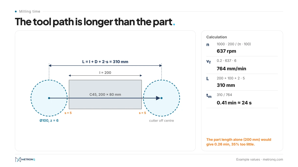
One pass takes , about 24 seconds, even though the surface itself is only 200 mm long. If the time were calculated from the workpiece length alone, the result would be more than a third too short. With a depth of cut of the removal rate is .
For peripheral milling the SME handbook gives a separate formula for the approach, the distance the cutter must travel before it cuts at full depth: , where is the cutter radius and the depth of cut. In the handbook example a side milling cutter with a radius of 4 in at a depth of 1.4 in has an approach of 3.04 in, which is more than the length of the machined surface itself (2.375 in).
SME calculates the operation cost as the sum of the labour rate, machine rate and miscellaneous costs multiplied by the time. At a rate of 60 EUR per hour (example value), the pass in the example costs 0.41 EUR. A 30-minute machine setup costs 30 EUR at the same rate: for a single part that is almost the whole cost, for 50 parts 0.60 EUR per part. That is why in a milling quote the setup time often weighs more than the cutting time, as we show in the article on the most expensive minute in CNC machining. MetronQ CNC quoting software performs these calculations automatically for every operation, using the shop's own rates and machines.
Accuracy and surface roughness after milling
Milling accuracy depends on the machining stage, the rigidity of the setup and the material. Roughing typically achieves IT12-IT14 and finish milling IT8-IT9, as we explain in the article on IT tolerance grades. Tighter tolerances require extra passes, reaming or grinding, which raises the cost.
Swift and Booker give a surface roughness of 0.2 to 25 µm Ra for milling, depending on the tool, parameters and pass. Typical finish milling usually achieves Ra 1.6-3.2. The result depends on feed per tooth, insert runout and milling direction, and wiper inserts allow a higher feed without a worse surface. More on Ra and Rz is in the article on surface roughness.
For the position of holes on CNC milling centres, the same handbook shows a process capability chart. At a dimension of 100 mm the normal range is roughly ±0.015-0.05 mm, as read from the chart. According to the authors, accuracy is affected above all by the machinability of the material and the rigidity of the cutter, workpiece and machine. How a position tolerance is specified is explained in the article on form and position tolerances.
How to design milled parts that cost less
A milled part is cheaper when the tool can reach it easily, works with a short overhang and needs few setups. Most of these rules follow directly from the geometry of milling. A designer who knows them can lower the price of a part without changing its function, before the request for quotation even reaches the shop.
The first rule concerns internal corners. A cutter is a cylinder, so it cannot produce a vertical pocket corner with a radius smaller than its own radius. A sharp internal corner requires EDM or another extra operation, and a very small radius means a small cutter and slow machining. A corner radius slightly larger than the cutter radius lets the tool move on an arc without a sudden rise in engagement.
The second rule concerns depth. A deep, narrow pocket needs a long, slender cutter, and the deflection of a cantilever beam grows with the cube of its length, according to . Twice the overhang means eight times the deflection under the same force, so depth or feed has to be reduced and the time gets longer.
Swift and Booker add rules on edges and tools. On external edges chamfers are preferable to radii, and dimensions and shapes are best matched to standard cutters. General rules complete the list: features accessible from one side, the same radii throughout the part, and tolerances only where the function requires them. How tolerances affect price is covered in the article on tolerances and CNC machining cost.
Frequently asked questions about CNC milling
How does CNC milling work?
CNC milling removes material with a rotating multi-tooth tool, the milling cutter, while program-controlled feed motions move the tool relative to the workpiece. Each tooth cuts for part of a revolution, so the cut is interrupted. The process produces flat faces, shoulders, slots, pockets, contours and 3D surfaces, mainly on prismatic parts such as housings, plates and brackets.
What is the difference between down milling and up milling?
In down milling the feed runs with the teeth in the cutting zone, and the chip starts thick and ends thin. In up milling the chip grows from zero, the edge first rubs, and the forces lift the workpiece. Down milling usually gives longer tool life and a better surface, but needs a backlash-free drive.
When should up milling be used?
Up milling is used when the machine has backlash in the feed drive, for example on an old manual milling machine. According to Sandvik Coromant it is also worth considering with large variations in machining allowance and with ceramic inserts in heat-resistant alloys. On modern CNC machines with backlash-free drives, down milling remains the first choice.
What surface roughness and accuracy does milling achieve?
According to the handbook by Swift and Booker, milling gives a surface roughness of 0.2 to 25 µm Ra, and typical finish milling ends at Ra 1.6-3.2. Rough milling usually achieves IT12-IT14 and finish milling IT8-IT9. Tighter tolerances need extra passes or a different method, for example reaming or grinding.
How do you calculate milling time?
Milling time is the tool path length divided by the table feed , which is the product of feed per tooth, spindle speed and number of teeth. The path includes approach and overtravel. In face milling with a cutter that passes fully over the surface, the path is the workpiece length plus the cutter diameter plus two safety clearances.
What is the difference between a 3-axis and a 5-axis milling machine?
A 3-axis milling machine moves the tool relative to the workpiece in the linear axes X, Y and Z. A 5-axis machine adds two rotary axes that tilt the workpiece or the spindle. A part can then be machined from several sides in one setup, and blades or moulds can be milled with all axes moving continuously.
Sources
- 1.K. G. Swift, J. D. Booker, "Manufacturing Process Selection Handbook", Butterworth-Heinemann 2013, chapter 6.2 Milling
- 2.Society of Manufacturing Engineers, "Realistic Cost Estimating for Manufacturing", 3rd edition, SME 2016, chapter 6: Cost Estimating for Machining
- 3.Sandvik Coromant, "Formulas and definitions for milling" and Metal cutting knowledge: "Down milling vs. up milling", "Face milling"
- 4.Mitsubishi Materials, Technical course: "Up cut and down cut milling"
- 5.Washington University in St. Louis, McKelvey School of Engineering Student Machine Shops, "Climb milling vs conventional milling"
- 6.ISO 841:2001, Industrial automation systems and integration - Numerical control of machines - Coordinate system and motion nomenclature
Read next
Automatic CNC machining quotes
Priced from the 3D model or the drawing, on your machines and your rates. You just approve it. 8 free quotes to start and 1 every month, no card.
Create a free account